Focal length by displacement is a method of estimating focal length of a lens where we change the position of a lens and observe the image formed on a screen while distance between object and the lenses is unchanged.
Ensure you have the following apparatus:
Lens HolderThe screencross wiresbulb as a source of lightcandle as a source of light
metre rule
Procedure to estimate focal length by displacement
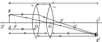
Set the apparatus as in figure below ensuring that the distance between the object and the screen is more than 4f where f is the focal length estimated above.
Obtain the image of the illuminated object on the screen when the lens is at position L1
move the lens to position L2 where another clear but diminished image is formed on the screen as Without changing the position of the object on the screen, shown below.
measure u and v for position L1 and the new distance u1 and v1 for position L2.
Determine the displacement d .
Deriving the displacement formular
from the diagram above, the distance between the point object and the screen is s. from the diagram, it is shown that the distance s is given by u+v.
Advertisement
i. e. s = u+v ………………………………..(1)
we get the distance between new and original position of the lens by use of expressions:
d=u’- u where u’ is the new object distance and u the original object distance
d can also be obtained from v-v’ which is the original image distance and image distance when the lens is displaced by distance d.
i.e d=u’-u and d = v-v’
but u’=v and v’=u
and therefore:
d=v-u………………………………….(2)
adding (1) and (2);
hence s+ d= u + v + v –u
and so: s + d = 2v and hence;
$$V = \frac{s+d}{2}$$
similarly we can subtract equation 2 from 1 as shown:
hence s- d = u + v –v + u
therefore : s- d = 2u and hence;
$$u = \frac{s-d}{2}$$
from the lens formulae:
$$\frac{1}{f} = \frac{1}{u}+\frac{1}{v}$$
we can substitute values of u and v in terms of s and d as obtained in the expressions above. And hence;
Estimating the focal length of a lens is a fundamental experiment in optics. It helps learners understand how lenses form images and bend light. Focal length is the distance between the optical center of a lens and its principal focus. Focal length determines how strongly the lens converges or diverges light rays. In this topic, students explore practical methods of measuring focal length using simple laboratory setups. This includes forming sharp images of distant objects or using object–image distance measurements. Through this investigation, learners develop essential skills in observation, measurement, and application of lens formulas, building a strong foundation for further studies in physics and optical instruments.
We can always determine the focal length of the given lenses by applying various methods of estimating focal length of a lens.
This methods may includes:
Focusing on a distance object
lens formula experiments
Using non-parallax method
Using an illuminated object
Displacement method
Page Contents
Focusing a distance object to estimate focal length
We arrange the white screen, convex lens on a lens holder and ruler such that rays of light from a distance object are incident on a lens that is close to the white screen.
See the diagram below
We adjust the lens position to and fro until we obtain a sharp image of a distance object on the screen.
Distance object means an object that is at large distance relative to the focal length of the lens. For instance an object 30 metre from a lens whose focal length is 21cm is a distance object. We note that, object position is many times longer compared to the focal length of the lens.
Distance between the lens and screen where the sharp image of a distance object is formed is considered to be the focal length of the lens. The area occupied by the image is the focal plane of the lens.
The estimated focal length is not exact but can be 2 cm plus or minus the real focal length.
This method of estimating focal length depends on the fact that parallel rays from infinity converges at the focal point on the screen.
Non-parallax method of estimating focal length
Parallax is a displacement or difference in the apparent position of an object viewed along two different lines of sight and is measured by the angle of inclination between those two lines.
Non-parallax is therefore when there is no difference in apparent position when an object is viewed along two different lines of sight.
An optical pin fixed on a cork that is supported by a clamp is placed above a lens that is on the mirror as shown below. The cork is such that it slides up and down the glass rod. see the diagram below.
Adjust height of the pin until it’s image is seen on the mirror.
The position of the pin is adjusted until the image from the mirror and the object pin seems to be moving together when you move your eyes.
Distance between lens and the pin when there is no parallax between image and object is the focal length of the lens.
Non-parallax: Using an illuminated object to estimate focal length
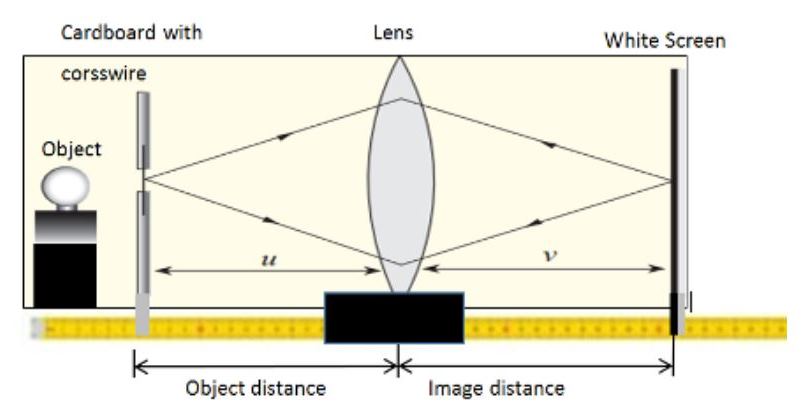
A bulb is placed behind a hole with a cross wire on a cardboard so as shown in figure below. A lens on a lens holder is placed between a mirror and the cardboard.
The cardboard together with the source of light is moved along the metre rule until a sharp image of the cross wire is formed along the cross wire object as shown. The figure shows two rays emerging from the point source towards the mirror through the lens
The lengths f gives the focal length of the lens.
Explanation
The ray striking the mirror are reflected back along the same paths of the incidence so that the image of the source coincides with the source itself. This image can be received on a screen placed at the same position as the source as shown.
If both lens and the mirror are perfectly vertical or parallel , image coincidesperfectly with the illuminated crosswire. This makes it hard to see when Estimating focal length.
It is therefore necessary to tilt either the lens or the mirror a little so that the image can be mapped besides the hole.
In the above arrangement, the object pin is moved towards the lens or away until it coincides with it’s inverted image. This occurs when the pinhead is vertically above the center of the lens.
At a point where the object and the image perfectly coincides, there is no relative motion between them. As the eye is moved perpendicular to them, they all move together as one.
The distance between the pin and the lens is then measured as the focal length of the lense.
NB: Focal length increases as thickness of the lens decreases. This is because thick lenses refracts and deviates light more sharply than a thin lenses. Therefore, rays emerging from thick lens tends to converge earlier because because of the sharp bending in the lens.
Determining Focal length from lens formula involves doing experiments to find different positions of image while adjusting object positions.
Focal length of a lens can be determined by investigating relationship between image distance and object distance by obtaining image distances from varying object distances.
The mirror formula describes the relationship that exists between the focal length, image distance and the object distance. Using the mirror formula derived earlier, We describe the experiment here and explains how to extract the the focal length from the relationship.
The mirror describes the relationship that exists between the focal length, image distance and the object distance.
The unknown Focal length of a lens can be determined experimentally by use of lens formula derived earlier. We describe the experiment here and explains how to extract the the focal length from the relationship.
We draw the graph of the of reciprocal values of image distance against the reciprocal values of object distance. The intercept of the graph is used to estimate the focal length of the lens used.
Apparatus
Metre rule
lens and a lens holder
source of light
screen
cardboard with a cross wire
procedure
set the apparatus as shown
You place the object at the zero centimeter mark
set the object distance by placing the lens at a reasonable distance from the object like 80cm from the object.
Adjust the screen to observe a sharp image on the screen.
Record a distance between the screen and the lens where you spot a sharp image on the screen is the image distance.
Record the image and the object distance
Reduce the object distance u by about 5 cm then adjust the screen until you see another sharp image on the screen.
reduce the distances distance again by 5 cm and repeat the procedure above.
Fill the table as shown below
From the data obtain a graph of 1/u against 1/v by plotting.
A typical graph will be as shown:
Graphical analysis of theLens formula
The lens formula is stated as:
1f=1u+1v
From the above formula, one can see that the sum of reciprocals of the image length from the lens and the reciprocal of the image distances equals reciprocal of the focal length.
At the (1/v) intercept the value of (1/u)= 0. The lens formular becomes:
1f=0+1v
We eliminated 1/u from the formula after it become zero such that:
1f=1v
The value of f-1 (1/f) is equal to 1/v meaning that we can approximate the reciprocal of f as the reciprocal of the image distance v read at the intercept.
At the (1/u) intercept, the the value of (1/v) =0. The lens formula becomes
1f=1u+0
The formular is reduced to be as follow:
1f=1u
Determining theFocal length from lens formula
as a process of Determining Focal length from lens formula, from the graph, we can deduce that 1/u and 1/v gives reciprocal of the Focal length 1/f at the intercepts.
we can get two values of f from the 1/v and 1/u intercepts such that:
f1=(1V)−1andf2=(1U)−1
The focal length f is the average of f1 and f2 such that:
f=f1+f22
Question for practice
The table below shows values of object distance u and corresponding value of image distances a for a convex lens.
object distance u(cm)
10
15
20
25
30
35
image distance v(cm)
40.0
17.1
13.1
11.8
10.9
10.4
a table showing relationship between image distance and object distance
plot a suitable graph and from the graph determine the focal length of the lens.
Introduction to thin lenses involves general description about properties of thin lenses.
A lens can be defined as a piece of curved glass or plastic that makes things look larger, smaller or clearer when you look through it.
In human eye, one component is a lens and so we can also define lens as the transparent part of the eye, behind the pupil, that focuses light so that you can see clearly.
The idea behind lens operations is that when a light ray passes from air which is more optically denser than the lens material, it is refracted.
When many rays passes through the lens, they all refracted the same way and so they meet at a common point. Sometimes they don’t meet but instead they are scattered after refraction but they are seemed to be spreading from a common point.
Lenses are usually made of glass, transparent plastic or perspex.
common application of lenses includes cameras, spectacles,telescopes, microscopes, film projectors and the human eye.
A thin lens means a lens whose thickness is negligible compared to the radius of curvature of the lens surfaces.
Types of thin lenses
The basic two types of lenses are convex and concave lenses.
Convex lenses are also called converging lenses as they cause the rays that passes through it to meet at a point. Convex lenses are thickest at the middle and they thin in as you move towards their edge.
In this lesson we will be talking about biconvex lenses meaning that it is symmetrical if we cut it long it’s edges. Both sides of it’s services at the center are bulging outwards and the edges are curved inwards uniformly on both sides.see the figure below
Bi convex lensshowing symmetrical in bi-convex lens
Concave lenses are also called diverging lenses as they cause the rays passing through them to be spreading from a common pint. Concave lenses are thinnest at the middle and they they become thicker as you move towards the edges.
There are variations of convex and concave lenses as illustrated in figures below
plano convex lensconvex meniscus lensplano concave lensconcave meniscus lens
Effects of lenses on Parallel rays of light
A cardboard with parallel slits is placed between the mirror and a bi-convex lens as in figure below
The mirror is set such that it reflects the sun rays so that the rays passes through the slits before they reach the lens.
After making observations, the bi-convex lens is replaced with a concave lens
Observation
when a convex lens is used, the rays are converged at a point on the paper and then diverge as they continue as shown.
illustrations of parallel rays as they pass through a bi-convex lens
When concave lens is used , the rays diverge as if they were from the focal point in front of the lens as shown.
illustrations of parallel rays as they pass through a biconcave lens
Investigating convergence and divergence of light by thin lenses using a ray box
A ray box acts as a source of parallel beam. A spot light can also be used.
A parallel beam is directed incident to the the lens as shown
Parallel rays of light incident to a convex lens
A white paper is placed on the other side of the lens and it’s position adjusted until a sharp point is observed.
observation
When a convex lens is used, the rays are converged at a point on the paper and then diverges as they continue as shown below
Parallel beam after passing through a converging lens
If convex lens was replaced with concave (diverging) lens, the rays will be observed diverging as if they are coming from a point on the other side of the lens. see the diagram below.
Parallel beam incident to diverging lens
Explanations
Light is usually refracted when it passes through a glass prism. A lens can be considered as an assembly of many tiny prisms where each prism refracts light as in figure below.
Illustrations of bi-convex lens as an assembly of prisms
Please note that, the middle part of the prism is like a rectangular glass prism and a ray that is incident to it at a perpendicular angle passes through without being refracted. As we may see in other lessons, a ray of light that passes normally through the geometrical center of the lens, passes through undeviated.
The figure below shows representation of concave lens as an assembly of prisms.
illustrations of concave lens as an assembly of prisms
conclusions
Rays of light that passes through a lens converges at a fixed point from the lens if the lens is a converging lens or diverge from a common imaginary point if the lens is a diverging lens.
The point at which the rays emerging from the lens converge or seems to diverge from is referred to as theprincipal focus.
A convex lens has a real principal focus while a concave lens has a virtual (imaginary) principal focus.
Thin Lens Ray Diagrams are useful in books, where use ray diagrams to represent images formed by thin lenses. Ray diagrams are straight lines with arrows that shows direction of light rays.
Points to note when drawing ray diagrams
when drawing real rays you should used complete solid lines but when drawing virtual images you should use broken lines.
To locate the image, you draw two of the three important rays from tip of the object towards the lens. The first ray parallel to principal axis and through principal focus and the second ray from the tip of the object through the optical center or the third that passes through the principal focus before moving parallel to the principal axis.
Where two or more rays intersect after refraction by the lenses is the tip of the image.
if the object stands and is perpendicular to the principal axis, the image is also perpendicular to the principal axis.
To complete the image, you draw a line perpendicular to the principal axis from the tip of the image
If the foot of the object crosses the principal axis, you draw two of the three rays used to locate image for both the tip and the foot of the object. You should join a point object for the image tip with point image of the foot to get the desired image.
You should represent converging lenses are by the following diagram in drawings:
Thin lens symbols
The figure below shows how we represent convex(convergence lens) on a diagram.
symbol used for convex lens
You represents concave lenses in diagrams by the symbol shown.
symbol for concave lens
An object image is usually represented by a straight arrow that is upright but when the image or the object is upside down, the arrow is upside down.
An upright arrow representing an object in ray diagrams
After we have identified the symbols, we can now use the three important rays discussed earlier to represent the ray diagrams.
After the object is drawn and image obtained from the ray diagram, the image formed can be studied by observing it’s nature after drawing.
Example problem on Drawing Ray Diagrams
An object 15cm tall has been placed 32cm from a concave lens of focal length 20 cm. By scale drawing, determine:
(a) position of the image formed
(b) Magnification of the image
(c) The height of the image
solution
We use the scale of 1 cm to represent 5 cm and using two rays to form an image, the resultant image after reflection is as shown
(a) From the diagram, one can see that the image is formed 52cm from the lense.
(b) From the diagram, the height of the image from the principal axis is 24 cm.
$$Magmification(M) = \frac{\text{height of image }(h_i)}{\text{height of object} (h_o)}$$
substituting for the values of hi and ho, we have:
$$M = \frac{24.5 cm}{15.0 cm}=1.633$$
The same result could be obtained by finding ration of image distance to object distance with some slight variation that comes with measurement errors:
(c ) From the scale diagram, the height of the image is about 24.5cm
Remarks:
The diagram can aslo be used to give further insights about the image formed. For example we can see that it is upside down and is formed by two rays actually meeting therefore it is a real image.
Also the image is taller than the object and hence it is magnified just by looking
Practice questions
An object placed in front of a convex lens of focal length 10cm produces an image at a distance of 15cm from the lens and on the same side as the object. By drawing a suitable diagram, Determine the position, nature and size of the object.
Questions involving pressure are physics questions that test your understanding of the concept of pressure, how it is calculated, and how it applies in solids, liquids, and gases.
They may involve:
Calculating pressure using formulas
Explaining real-life applications
Understanding liquid pressure
Understanding atmospheric pressure
Applying Blaise Pascal’s Principle
The figure below shows Hare’s apparatus used for comparing liquid densities.
Use the information given in the above diagram to calculate the density of liquid x given that density of water is 1000kgm-3 (2mks)
A thin lens is a transparent piece of glass or plastic that is curved on one or both sides and is used to bend (refract) light rays. It is called thin because its thickness is very small compared to its radius of curvature. Thin lenses are commonly used in optical instruments such as Cameras, Microscopes, and Telescopes to form images of objects. When light passes through a thin lens, it changes direction and either converges to form a real image or diverges to form a virtual image depending on the type of lens. Thin lenses have their own language and vocabulary.
Having the Language of thin lenses means that thin lenses have their own vocabulary mostly that describes various parts of the lens. This parts includes:
Center of curvature C
Radius of curvature R
Principal axis P
optical center O
Principle Focus F
Focal Length f
Focal plane
We will discuss all the highlighted parts in this lesson
It is defined as the center of the sphere of which the surface of the lens is part.
We consider the lens to have been cut off from a transparent sphere of radius R. In other word, the lens is part of a curved surface of a certain sphere as illustrated below.
For bi-convex lens, the lens is considered to come from two pieces cut from two different spheres and combined at the inner side. Consider the illustration below where we extract service1 and service2 from two spheres.
sphere for surface1sphere for surface2
Because the bi-convex comes from two spheres, it will have two centers of curvature which will be opposite to each other.
similarly the bi-concave lens is derived from two spheres as illustrated.
Different parts from spheres will be joined two have a concave lens that has two centers of curvature as shown below
Radius of curvature
It can be defined as the radius of the sphere from which the surface of the lens is part.
It can also be defined as the distance between the Center of curvature and the optical center o of the lens.
Principal axis
It is an imaginary line passing through the centers of curvature and is perpendicular to the plane of the lens.
Optical center
It is the geometric center of the lenses where a ray incident to the lens passes on undeviated.
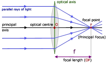
Principal focus
Sometimes also referred to as the focal point, It is a point on the principal axis where rays parallel and close to the principal axis converge after refraction by a convex lens or where the rays parallel and close to the principal axis seems to diverge from after refraction by a concave lens.
The figure below illustrates convergence of parallel rays of light at principal focus after refraction.
showing a principal focus of a convex lens
The virtual principal focus of a concave lens is as illustrated below
A lens has two principal foci, and they are on either side of the lens.
The principal focus of converging lens is said to be real because their actual meeting of rays of light there.
The principal axis of diverging lens is said to be virtual (imaginary) because rays of light do not actually meet there.
Rays that are parallel and close to the principal axis or almost parallel to the principal axis are referred to us paraxial rays.
Rays parallel but far from the principal axis are referred to as marginal rays or axial rays.
Focal length f
It is the distance between the optical center of the lens and it’s principal focus.
By Convection, focal length of converging lens is considered real while that of diverging is considered virtual.
Focal plane
It is an imaginary plane that passes through the focal point and is perpendicular to the principal axis.
Focal plane is illustrated below
rays of light that are not parallel to the principal axis converges at a point on a focal plane or will appear to diverge from there after refraction
Conclusion
In this lesson we have seen that lens are pictured as being extracted from a sphere and the radius of the said sphere plays and important role in description of the lens. A lens converge or diverges rays parallel to the principal axis at the focal point.
A perfect square is a number that is obtained when a whole number is multiplied by itself. In other words, it is the result of squaring an integer. For example, 1=1×11=1×11=1×1, 4=2×24=2×24=2×2, 9=3×39=3×39=3×3, and 16=4×416=4×416=4×4. These numbers are called perfect squares because they can be arranged to form a perfect square shape.
Perfect squares are important in mathematics because they help us understand square roots, area, and patterns in numbers. The square root of a perfect square is always a whole number. For instance, the square root of 25 is 5, since 5×5=255×5=255×5=25.
in quadratic expressions, a perfect square occurs when the expression can be written as the square of a binomial. This means the quadratic can be expressed in the form:(a+b)2or(a−b)2
When expanded, these forms follow special patterns:
A quadratic expression is called a perfect square trinomial if:
The first term is a perfect square.
The last term is a perfect square.
The middle term is twice the product of the square roots of the first and last terms.
Examples
x2+6x+9 is a perfect square
x2 = (x) x (x) =(x)2
9 = 3 x 3 = (3)2
middle term : 6x = 2(x)(3)
Therefore:
x2+6x+9 = (x+3)2
Example 2
assume x2−10x+25 is a perfect square
x2 = (x) (x) = (x)2
25 = (5)2
middle term:-10x = -2(x)(5)
therefore x2−10x+25 = (x-5)2
Importance in Solving Quadratics
Perfect square expressions are useful because:
They make factorization easier.
They help in completing the square, a method used to solve quadratic equations.
They simplify graphing, since expressions like clearly show the vertex of a parabola.
Example problem
factorize x2 – 8x +16
solution
The constant term is a perfect square
middle term is twice the constant term
hence 16 = (4)(4)
-8 = -4-4
hence x2 – 8x +16 = (x-4)(x-4) = (x-4)2
example
factorize:
$$x^2+\frac{4}{3}x+\frac{4}{9}$$
solution
$$\frac{4}{9} = \frac{2}{3} \ or \ (\frac{-2}{3})$$
Completing the square is a method used to solve quadratic equations and rewrite quadratic expressions in a special form. It helps us change a quadratic expression into a perfect square trinomial, which can then be factored easily.
consider the expression x2 +bx
we can add a constant term such that the expression becomes a perfect square.
To complete the square:
Take half of ,square it and then add it to the expression.
that is: add (b/2)2 to the expression
Example problem on completing the square
what must be added to x2 -18x to make it a perfect square?
$$\text{we must add}: (\frac{1}{2} \times (-18)^2 =(-9)^2 =81$$
so x2 -18x is transformed to x2 -18x+81 to be a perfect square.
Upthrust in gases is the upward force exerted on an object immersed in a gas, which opposes the object’s weight. Upthrust in gases acts as an upward force on an object immersed in a gas and opposes the object’s weight. It arises from the pressure difference between the top and bottom of the object due to the gas’s density. This concept is similar to upthrust in liquids but involves the behavior of gases, which are much less dense than liquids.
When an object is placed in a gas, the pressure at the bottom of the object is greater than the pressure at the top. This difference in pressure results in an upward force (upthrust). This is what that results to upthrust in gases. The size of this force depends on the volume of the displaced gas and the density of the gas.
Just like liquids, gases exerts upthrust on objects that are in them. Air is the most common gas of interest and so it will be used extensively to illustrate upthrust in gases. We float objects on air. Sometimes, as human beings, we use parachutes to float in air.
The upthrust in gases is small because air has lower density compared to most of substances.
The density of air is about 1.3kgm-3 or 0.0013gcm-3.
A balloon can float in air if it contains a gas with a lower density than air. For example hydrogen has a density of 0.09 kgm-3 whereas helium has a density of 0.18kgm-3. Therefore a balloon filled with helium or hydrogen will rise on air provided density of the balloon fabric and air will be less than density of air.
Problems involving upthrust in gases
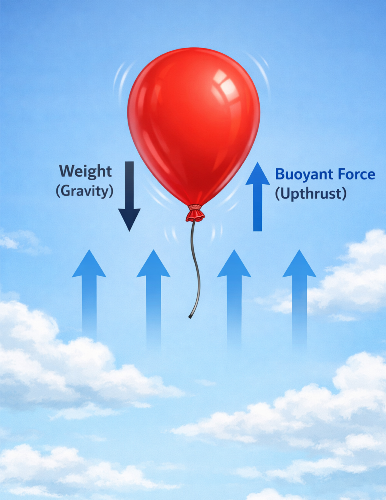
Consider the figure below that illustrates a balloon filled with air .
If we consider the balloon filled with air to a certain volume, the weight of air in the balloon plus its fabric is greater than the weight of air displaced. This is because the volume of air in the balloon is nearly equal to the volume of air displaced.
The upthrust force on the balloon due to the air is thus less than the weight. The balloon thus stay grounded because the it’s weight is less than the upthrust force that could set it up to float on air.
That is W-U > resultant downward forces.
If the balloon is filled with a gas that has a lower density than air, the gas and balloon fabric weigh less than the displaced air. The upthrust force U exerted by the air on the balloon is greater than the weight W of the inflated balloon. This results in the upthrust force being larger. The resultant upward force is greater than W-U and hence the balloon sets to accelerate upward.see the illustrations below.
Example Question
A meteorological balloon has a volume of of 55m3 and is filled with a helium gas of density 0.18kgm-3. If the weight of the balloon fabric is 170N, calculate the maximum load the balloon can lift given that density of air is 1.3kgm-3
solution
Volume of air displaced by the balloon is 55m3 which is volume occupied by the balloon.
mass of air displaced by the balloon = 55m3 x 1.3kgm-3 = 71.5kg
weight of air displaced =71.5kg x 10 Nkg-1 = 715N
mass of helium in the balloon = 55m3 x 0.18kgm-3 = 9.9Kg
weight of helium in the ballon = 9.9kg x 10 Nkg-1 = 99N
Total weight of the inflated balloon = 170N + 99N = 269 N
From the law of floatation, upthrust is the weight of air displaced which should also be weight of the balloon plus the weight of load it will carry. hence,
upthrust = weight of the balloon + load in the ballon = weight of air displaced
269N + load in the ballon = 715N
load in the balloon = (715-269)N=446N
So the total mass of the goods to be included in the balloon should never exceeded 44.6kg.
Alphabetical letters are the basic symbols used to form words and communicate ideas in written language. They help us read, write, and understand information in an organized and meaningful way.
Contains information related to marketing campaigns of the user. These are shared with Google AdWords / Google Ads when the Google Ads and Google Analytics accounts are linked together.
90 days
__utma
ID used to identify users and sessions
2 years after last activity
__utmt
Used to monitor number of Google Analytics server requests
10 minutes
__utmb
Used to distinguish new sessions and visits. This cookie is set when the GA.js javascript library is loaded and there is no existing __utmb cookie. The cookie is updated every time data is sent to the Google Analytics server.
30 minutes after last activity
__utmc
Used only with old Urchin versions of Google Analytics and not with GA.js. Was used to distinguish between new sessions and visits at the end of a session.
End of session (browser)
__utmz
Contains information about the traffic source or campaign that directed user to the website. The cookie is set when the GA.js javascript is loaded and updated when data is sent to the Google Anaytics server
6 months after last activity
__utmv
Contains custom information set by the web developer via the _setCustomVar method in Google Analytics. This cookie is updated every time new data is sent to the Google Analytics server.
2 years after last activity
__utmx
Used to determine whether a user is included in an A / B or Multivariate test.
18 months
_ga
ID used to identify users
2 years
_gali
Used by Google Analytics to determine which links on a page are being clicked
30 seconds
_ga_
ID used to identify users
2 years
_gid
ID used to identify users for 24 hours after last activity
24 hours
_gat
Used to monitor number of Google Analytics server requests when using Google Tag Manager