Energy of the x-rays are energy possessed by x-rays radiations. X -rays are electromagnetic waves of very short wavelengths of order 10-10 m. Therefore x-rays carries energies according to plank’s theory. The wavelength of the x-rays overlaps with that ultraviolet and gamma rays in electromagnetic spectrum. This is because X-rays are classified in the range 10-11 to 10-8 in electromagnetic spectrum.
Determining Energy of the x-rays
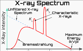
If a bombarding electron is stopped in a single collision, some or all it’s energy is converted to X-ray energy. At a given accelerating potential difference, the X-rays produced will have varying wavelengths . The minimum wavelength (λmin) corresponds with a collision in which all the kinetic energy in the motion is converted to x-rays.
The kinetic energy (K.E) of the bombarding electron is practically equal to eV. This energy is expressed as. K.E = ev where V is the accelerating potential and e the charge on an electron.
When all the kinetic energy of an electron is used to produce x-ray waves, the frequency of the x-rays produced will be maximum. This maximum frequency is expressed as fmax.
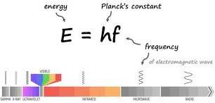
Using Plank’s theory, the X-ray energy is given by: E= hf. where h is the Plank’s constant and f the frequency of the radiation.
eV = hfmax
remember that speed of a wave is given by the general equation v=fλ. But x-rays being part of electromagnetic spectrum moves at a speed of light represented by c.
Hence the speed of the x-ray waves will be c= fλ, c being the speed of light.(c=3.0 x 10⁸ ms-1)
Therefore the speed of the x-ray waves produced will be given by: c = fmaxλmin.
we now express frequency of the x-ray produced in terms of speed and wavelength:
From the equation, we see that the most energetic X-rays have the shortest wavelength.
Example problem on energy of the x-rays
Find the frequency and the energy of a type of X-rays whose wavelength is 10-10 m. (velocity of light c = 3.0 x 10⁸ ms-1, Plank’s constant h = 6.63 x 10⁻³⁴ Js).
solution
c=fλ
$$ f = \frac{c}{\lambda} $$
$$ f = {3.0 \times 10^8}{10^{-10}} = 3.0 \times 10^{18}Hz $$
E=hf
E = 6.63 x 10-34 x 3.0 x 1018 = 1.989 x 10⁻¹⁵J
practice Questions
1. The frequency of X-rays ranges from 3.0 x 10¹⁷ to 3.0 x 10¹⁹Hz. Determine
(a) the range of the wavelengths.
(b) the maximum energy of the X-rays. (velocity of light c= 3.0 x 10⁸ms-1 and plank’s constant h= 6.63 x 10⁻³⁴Js)
2. An X-ray tube has an accelerating potential difference of 100 Kv. what is the shortest wavelength in its X-beam? Take plank’s constant h=6.63 x 10⁻³⁴Js, charge on an electron e = 1.6 x 10⁻¹⁹C and velocity of light c = 3.0 x 10⁸ms-1.
hard x-rays
X-rays are usually classified as hard or soft. Hard x-rays are described as having high frequency hence shorter wavelengths and so high penetrating power. Hard X-rays are produced by use of high accelerating voltage that causes the electrons move at very high speed towards the target in the x-ray tube.
soft x-rays
Soft X-rays are produced by electrons moving at relatively lower velocities . They are of less energy and lower frequency. Specifically, they fall within the 100-3,000 eV energy range. Due to their lower energy, soft X-rays are more readily absorbed by matter and have limited penetrating power, requiring measurements to be conducted in a vacuum. They are valuable for studying surfaces, near-surface interfaces, and for spectroscopic techniques like X-ray Absorption Spectroscopy (XAS) and X-ray Photoelectron Spectroscopy (XPS)
Examination questions on photoelectric effect involves key concepts like work function, threshold frequency, and the relationship between light frequency, photon energy, and electron kinetic energy. The photoelectric effect involves the emission of electrons from a metal surface when light shines on it. Here are some example exam questions:
Examination questions on photoelectric effect
1. (a) What is meant by threshold wavelength? (1 mark) (b) How does intensity of radiation incident on a metal surface affect the photoelectrons emitted. (1 mark) (c) In an experiment using a photocell, light of varying frequency but constant intensity was made to strike a metal surface. The maximum kinetic energy of the photoelectrons for each frequency, f, was measured. The values obtained are shown in table 2 below
Maximum K.E (x 10-19)
2.8
5.4
7.4
9.0
10.0
11.0
Frequency (x 1015) Hz
1.5
1.9
2.2
2.42
2.57
2.75
(i) Plot a graph of maximum K.E against frequency. (5 marks)
2. The fig. below shows a photo – cell.
What factor determine the kinetic energy of the electrons emitted, hence show the relationship. (2 marks)
3. (a) What is meant by the term photo – electric effect. (1 mark)
b) The figure below shows an arrangement used to investigate photo-electric effect.
(i) Name the parts marked P and Q. (2 marks)
(ii) State three measurable quantities in this set up. (3 marks)
(iii) State how the intensity of light affects the photo – current. (1 mark)
c) The results obtained for various monochromatic radiations of different colors are shown in the grid below.
(i) The graph indicates that there is a frequency below which no electrons are
emitted. explain why this is so. (1 mark)
(ii) From the graph determine;
(i) Plank’s constant, h (Take electron charge, e = 1.6 x 10⁻¹⁹C) (4 marks)
Exam Questions on work functions in photoelectric effect
(ii) The work function of the metal. (3 marks)
(iii) Sketch on the same graph, the expected graph of another metal which has a lower work function than the metal used. (1 mark)
4. The graph in Figure shows the variation of frequency of radiation f with the greatest kinetic energy of the emitted electrons.
From the graph determine
(i) Plank’s constant (4mks)
(ii) Hence or otherwise calculate the work function of the metal. (3mks)
5. (a) What do you understand by the term photoelectric effect? (1mk)
(b) Name one factor that determines the velocity of photoelectrons produced
on a metal surface when light shine on it. (1mk)
(c) In a photoelectric effect experiment, a certain surface was illuminated with
radiations of different wavelengths and the stopping potential determined
for each wavelength. The table in figure 9 below shows the results obtained.
Stopping potential (Vs) V
1.35
1.15
0.93
0.62
0.36
Wavelength (x 10-7m)
3.37
4.04
4.36
2.42
5.46
On the grid provided plot a graph of stopping potential (Y-axis) against frequency. (7mks)
6. The table below shows the kinetic energy of photoelectrons for various radiations for a given photo emissive surface.
kinetic energy (x 10-19)
0.42
1.47
2.10
2.73
3.36
3.78
Frequency x 1014 Hz
4.50
6.00
7.00
8.00
9.00
9.75
i) Plot a graph of kinetic energy (y axis) against the frequency (x – axis) (5mks)
ii) Use the graph to find h the Planck’s constant (2mks)
iii) From the graph determine the work function of the surface (2mks)
iv) State 3 factors that affect the photoelectric effect (3mks)
(v) State two applications of photoelectric effect (2 marks)
X-rays are produced when fast moving electrons are suddenly stopped by matter. An X-ray (Röntgen radiation) is a form of high-energy radiation with a wavelength shorter than those of ultraviolet rays and longer than those of gamma rays. X-rays were discovered in science as a type of unidentified radiation emanating from discharge tubes by experimenters investigating cathode rays. They were accidently noticed by a German scientist known as Wilhelm Röntgen. Röntgen, a professor of physics discovered X-rays while experimenting with Crookes tubes and began studying them on November 1985.
How x-rays are produced
X-rays are produced in x-ray tube where highly accelerated electrons are suddenly stopped by a metal target. Figure below shows the structure of an X-ray tube.
figure 1: an x-ray tube
How x-ray tube works
When a current flows through the filament in the cathode, electrons are produced by thermionic emission. Thermionic emission is the release of charged particles, usually electrons, from a heated surface, such as a metal. Electrons are then accelerated towards the target by a high potential difference of about 100Kv between the cathode and the anode. The metal target is the anode. Cathode is concave shaped in order to focus the electron beam produced towards the metal target. The metal target is usually composed of tungsten embedded onto copper.
Tungsten is preferred because of it’s high melting point. Copper is also preferred as it is a good conductor of heat. This ensures efficient dissipation of heat. A lot of heat is produced during x-ray production. This is because most of kinetic energy of the electrons are converted to heat when they heat a metal target. Only about 0.5 % of the kinetic energy is converted to x-ray radiations. Because heat produced is a lot, cooling is enhanced by the cooling fins on the outside of the tube and circulation of oil through the channels in the copper block(node).
modern x-ray tube
In an improved recent model of an x-ray tube, the target is designed to rotate during operation so as to change the point of impact. This reduces wear and tear resulting from frictional forces. The figure below shows the more modern x-ray tube.
figure 2: improved x-ray tube with rotating anode
X-ray tube is made up of strong highly evacuated glass. This ensures that no gaseous particles are inside to collide with the fast moving electrons. Collisions with air particles would cause electrons to loose some of their energy before they reach their target hence lacking enough energy to produce x-ray.
The target is usually set at an angle of 45o to the electron beam so that to direct x-rays out of the tube through a window on the lead shield. see figure 1 above. Incase some x-rays are produced at an angle that would make them unable to exit the tube, then they will be safely absorbed by the lead shield surrounding the tube. A step-up transformer is used to increase voltage from main supply so as to provide the high voltage required to accelerate electrons.
x-ray tube in application
properties of X-rays
They are not deflected by magnetic or electric fields. This shows that they carry no charge.
X-rays penetrate matter according to the density of matters. High density materials like lead are least penetrated by x-rays.
Affects photographic emulsions. This makes x-rays useful in x-ray photography.
They ionizes air molecules
causes fluorescence in certain substances such as zinc sulphide
X-rays are of shorter wavelengths compared to visible light.
They can be plane-polarized, be diffracted and be reflected
The Einstein’s Equation of Photoelectric Effect describes how energy of an electromagnetic rays incident onto metal surface is distributed. When an electromagnetic ray falls on a metal surface , the energy absorbed by the electron is divided into two:
Energy used to dislodge an electron from it’s orbit to the surface.
Energy used as a kinetic energy to accelerate an electron from the surface
The energy of a photon can thus be expressed as sum of two energies:
Energy of a photon
=
energy needed to dislodge an electron from metal surface
+
maximum kinetic energy gained by the electron
The work function
The minimum energy needed to dislodge an electron from a metal surface is called the work function (Wo) of the metal. Work function energy varies from metal to metal.
Work function is expressed in a unit called electron-volt(eV) or joules (J).
1 eV = 1.6 x 10⁻¹⁹J.
Emission of photoelectrons occurs only when frequency incident onto the metal surface is above certain value. The minimum frequency to provide energy required to dislodge an electron from the metal surface is usually referred to as the threshold frequency(fo) of the given metal.
From the genera equation of the electromagnetic waves: c = fλ, the corresponding wavelength for the threshold frequency is known as threshold wavelength (λo) .
wo = hfo
which can also be expressed as :
$$W_o =h\frac{c}{\lambda_0}$$
when any radiation is of frequency f that is lower than fo , The energy it gives (hf) will be lower than Wo .
when hf= hfo, electrons are dislodged from their atoms but they just remain on the metal surface. An extra energy will be required to move them from the surface. That can happen if the radiation has extra energy besides that which is enough just to dislodged an electron and brings it to the surface.
Kinetic energy of a photoelectron comes from what remains after part of the electromagnetic waves energy has been used to extract an electron.
Thus when a wave is carrying an energy greater greater than the work function, the excess energy appears as the kinetic energy of the emitted electron.
from our earlier expressions of the wave energy, we see that:
$$hf-W_o = \frac{1}{2}m_ev^2$$
me being the mass of an electron and v the velocity gained in the acceleration.
Thus total energy hf in a wave is usually expressed as:
$$hf = W_o + \frac{1}{2}m_ev^2$$
Einstein’ s Equation in terms of wavelength
since Wo = hfo the Einstein’s equation can be written as:
The table below shows work functions of some metals:
Example problems involving The Einstein’s Equation
Question one
The minimum frequency of light required to cause photo electric emission from potassium surface is 4.92 x 10¹⁴Hz. When the surface is irradiated using a certain source, photoelectrons are emitted with a speed of 6.51 x 10⁵ms-1. Determine
The work function of potassium
The maximum kinetic energy of the photoelectron
frequency of the source of radiation
(take h =6.63 x 10⁻³⁴Js and me = 911 x 10-31Kg)
solution
(1) by application of The Einstein’s Equation Wo = hfo
The threshold wavelength of a photoemmisive surface is 0.55\µm. calculate:
(a) its threshold frequency
(b) the work function in eV
(c) the maximum speed with which a photoelectron is emitted if the frequency of the radiation is 9.5 x 10¹⁴Hz(Take plank’s constant h=6.63 x 10⁻³⁴Js and me =9.11 x 10⁻³¹kg)
solution
(a) λo=0.55μm=5.5×10⁻⁷m
by using the general equation of speed of light:
$$c=f_o \lambda_o$$
$$\text{so that } f_o= \frac{c}{\lambda_o}$$
Assuming the area to be circular with a radius r, then we can express A in terms of r such that:
A = πr2 and the Intensity becomes
$$I= \frac{1}{A} \times P = \frac{P}{\pi r^2}$$
It can therefore be shown that, Intensity is inversely proportional to area.
consider the setup below:
Intensity of the radiation is varied by changing the distance between the source and the surface of the cathode (r). The corresponding values of current is then recorded.
From the experiment, one discovers that the current increases when distance r is reduced.
From the basic law of charges, current I is directly proportional to the number of electrons. That is I = ne. where n is the number of electrons and e is charge on a single electron.
Hence, the photocurrent is directly proportional to the number of photoelectrons emitted per second. We can therefore conclude that the number of photoelectrons produced is directly proportional to the intensity.
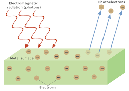
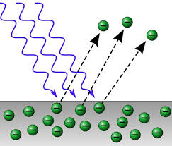
Photo electric effect is where we study behavior of metals when electromagnetic radiations falls on them. When we provide metals with some energy, the energy extracts electrons in their atoms causing them comes to the surface. This energy that extracts electrons from metal surface will come from heat energy or from electromagnetic radiations.
When Electromagnetic waves are incident onto a metal surface, some electrons gains enough energy to escape from the surface. For instance, when light energy falls on a negatively charged conductor, it becomes discharged.
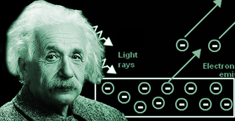
The emission of electrons by a metal exposed to light is known as the photoelectric effect.
The electrons the metal emits by photoelectric effect we refer to as photoelectrons.
A material that exhibits photoelectric effects we say that it is photoemmisive.
Illustrating Photo electric effect
To experiment on photo electric effects, you may need the following materials.
An electroscope
zinc plate
Emery paper
glass rod
silk cloth
Ebonite rod
piece of fur
Table lamp
Ultraviolet lamp
sheet of glass
Investigating photo electric effect
proceed as the follow:
Clean the surface of the zinc plate with emery paper and lay it on the electroscope cap.
Rub the glass rod with silk and charge the electroscope positively.
Shine light from the table lamp onto the zinc plate and observe if the electroscope leaf falls or rises
Repeat the steps above using ultraviolet lamp and observe if the electroscope leaf falls or rises
Discharge the electroscope and lay the zinc plate on it again
Rub the ebonite rod with fur and then charge the electroscope negatively
Shine light from the table lamp onto the zinc plate making the light as intense as possible by holding it as close as possible to the surface and see if the electroscope leaf falls or rises
Repeat 6 and 7 using ultraviolet lamp and observe if the electroscope leaf falls or rises.
Recharge the electroscope negatively and try to discharge it by shining ultraviolet light on the zinc plate as shown
As the leaf begins to fall, insert a sheet of glass between the lamp and the plate.
Observations on Photo electric effect experiment
visible light from table lamp was shone onto the positively charged electroscope but the leaf did not fall.
ultraviolet rays from ultra violet lamp are directed on to the positively charged electroscope but the leaf did not fall.
When visible light was shone onto the negatively charged electroscope, the leaf of the electroscope did not fall.
When ultraviolet rays were directed towards the negatively charged electroscope, the leaf of the electroscope falls.
A sheet of glass is placed between the violet lamp and the discharging electroscope and it stops the discharge. Discharging continues when it is removed.
Explaining the experiments on photoelectric effects
Neither visible light nor ultraviolet rays were able to discharge positively charged electroscope. This is because there are no electrons to be dislodged from positively charged electroscope. This suggests that the effects of radiations is to eject electrons which has negative charges from the metal surface.
The fact that visible light is not able to discharge a charged electroscope while the ultraviolet rays does suggests that not all the radiations can eject electrons from a metal surface. Ultra violet rays has a higher frequency compared to visible light suggesting that a certain minimum energy is required to eject electrons from a metal surface.
A sheet of glass stopping the discharging process suggests that the glass block absorbs the ultraviolet rays and so they are not able to penetrate through and reach the zinc plate.
One reason a positively charged electroscope is not discharged by radiations is that photoelectrons emitted from the positively charged zinc plate do not escape as they are neutralized by the positive charges on the plate and so the leaf divergence remains the same.
Illustrating photoelectric effect using a photocell
A photocell contains two metal electrodes sealed in an evacuated tube. The figure below shows a photocell circuit.
Evacuation of the tube prevents electrons from being stopped by air molecules.
The tube is usually made of quartz material in order to allow ultraviolet rays pass through easily. Electrons after being ejected at the cathode, they are attracted to the anode by a potential difference across the electrodes.
Before any radiation falls on the cathode, no deflection is noted on the galvanometer. This means that no current is flowing through the circuit. When a radiation of given frequency falls on the cathode, deflection is observed on the galvanometer meaning that current has been flowed through the circuit.
Electrons after being ejected from the cathode, are accelerated towards the anode by the potential difference hence the circuit is complete.
The quantum theory of light proposes that light travels in bundles of energy, known as a photon. In 1909, Max Plank proposed that light energy is propagated as a small packets of energy that are discrete. Each packet of energy is referred to as a quantum of energy. The discrete amount of energy are called photons and posses a definite energy that can be determined from the frequency of the light waves.
Energy E of a photon can be determined from the relation E=hf. Here, h is a constant value known as Plank’s constant. Max Plank introduced it in his theory.
Plank’s constant h is given as h=6.63 X 10⁻³⁴Js
From the general equation of a wave:
c=fλ
where λ is the distance between two particles in a wave usually referred to as the wavelength.
expressing f in terms of speed of light:
f=cλ
substituting for f in the equation E=hf;
$$E=h\frac{c}{f}$$
c is the speed of an electromagnetic radiation in vacuum and is given as 3.0 x 10⁸ms-1
c and h are constants in the equation and so energy of a wave is only determined by the wavelength. From the equation, energy increases when wavelength reduces.
Energy of a photon is therefore inversely proportional to the wavelength.
Example problem on the Quantum theory
compare energy contained in a photon of red light of wavelength 6.7 x 10⁻⁷ m and violet light of wavelength 3.4 x 10⁻⁷m. (take Plank’s constant as 6.63 X 10⁻³⁴Js)
solution
The energy carried by the red light will be given as :
Therefore energy carried by red light photon will be:
E = 5.85 X 10⁻¹⁹ Joules
As can be determined from the above working, violet light has more energy compared to red light as it has shorter wavelength.
Light energy in a Photons
Most of waves are considered continuous and progress as in figure below:
A continuous wave can carry any amount of energy depending on the amplitude and frequency. There is no minimum energy of the wave but energy may be reduced simply by decreasing amplitude of the wave.
Quantum theory however shows that electromagnetic waves travels as wave packets also known as photons that are imagined to travel as shown.
Each photon carries a definite amount of energy that is proportional to the frequency of the radiation.
Example problem
Determine an energy carried in a photon of an x-ray with a frequency of 8.0 x 10¹⁷ Hz.
solution
Energy E = hf
E=6.63×10−34Js×8.0×1017 Hz
=5.304 X 10⁻¹⁶ J
Threshold Frequency
Radiations below certain frequencies does not eject electrons from a metal surface no matter how intense the light will be.
The minimum frequency needed for a wave so that it is able to eject an electron from a metal surface is known as the threshold frequency fo.
If the frequency is below a certain value, it will be absorbed by the metal surface onto which it falls but no electron will be ejected to the surface.
Threshold wavelength
if the threshold frequency is fo ,the speed of the wave can be determined by:
c= foλo where λo is known as the threshold wavelength that corresponds with the threshold frequency. It is the maximum wavelength beyond which an electron wont be ejected from a metal surface.
in other words:
$$\lambda_o = \frac{c}{f_o}$$
The quantum theory: Work Function
The work function wo is the minimum amount of energy needed to eject an electron from a metal surface. It represents work that need to be done in order to remove a negatively charged electron from a metal atom by overcoming the force of attraction of the positively charged nuclei of the atom.
Different atoms have different magnitude of attractive forces between its nucleus and the electrons. This means different energy will be required to eject electrons from different metal surfaces. Therefore, the value of work function differs from one metal to another.
Some applications of C.R.O includes measuring of electrical potential as a voltmeter, television displays and in measuring frequency of signals.
applications of C.R.O as a voltmeter
C.R.O can be used as a voltmeter when it time base circuit is switched off and the voltage to be measured is connected across the Y-plates while the X-plates are earthed.
The vertical displacement of the bright spot on the screen is measured and the sensitivity of the C.R.O is adjusted to determine number of volts per units of displacement along the vertical scale.
The number of volts per unit of division is the sensitivity. The voltage can the be determined as:
Voltage = displacement x sensitivity
Sensitivity is adjusted using the Y-gain knob which automatically connects the input signal through an application system.
Amplification system ensures that even very signals are raised to the levels where they cause measurable deflection of the beam.
application of C.R.O as a voltmeter is considered a superior voltmeter compared to convectional ones because of the following reasons:
can measure large voltages without being damaged
can measure both direct and alternating voltages
Has infinite resistance hence takes no current meaning that it rarely interferes with the circuit into which it is being connected.
It responds instantaneously unlike ordinary meters whose meters swings momentarily about the correct reading due to inertial.
Example Problem on usage of C.R.O as a voltmeter
A D.C voltage of 80V when applied to the Y-plates of a C.R.O causes a deflection of the spot as shown in figure below:
(i) Determine sensitivity of the y-gain
(ii) show what will be formed on the screen if an a.c of peak voltage 64V
is fed onto the Plates.
solutions
(i)
spot deflection on the screen from the center of the screen = 5 divisions
Voltage in a.c with be a straight line 4 divisions above the central line and 4 divisions below it as shown below
Example applications of C.R.O
The Y-gain of a CRO has a sensitivity of 500V/div. An a.c voltage of 2500V is connected across the Y-plates. show what is observed on the screen.
solution
Voltage = sensitivity x number of divisions
We need to determine the number of divisions that a signal will be displaced vertically.
$$\text{Number of divisions} = \frac{voltage}{sensitivity} = \frac{2500 V}{500 V / div} = 5 divisions $$
Numberofdivisions=Voltagesensitivity
=2500V500v/div=5divisions
Hence a straight vertical line will be formed on the screen covering 5 divisions above the x-axis and 5 divisions below it as shown
applications of C.R.O to measure frequency of an a.c signal
The signal is fed into the Y_plates of a C.R.O with the time base on. The time base control is then adjusted to give one or more cycles of the input signal on the screen. By adjusting the time base control, we can determine the number of cycles made on the screen from the periodic time T. Frequency can then be calculated from f=1/T.
Example question on applications of C. R.O
Figure below shows a trace on the screen for an signal connected to the Y_plates of a CRO with time base on.
Given that the time base control is 20ms/div and the Y-gain is at 80V/div, determine:
(i) frequency of the a.c signal
(ii) The peak voltage of the input signal
solution (i)
Time base settings is 20ms/div
Number of waves shown on the screen =3.25
7 div is covered by 2.5 waves.
1 wave = 7.0/2.5 = 2.8 divisions
Time taken to complete 1 wave (periodic time) = 2.8 div x 20ms/div = 56ms = 56 x 10-3s
Frequency=1T
And so the frequency will be given by:
Frequency=156∗10−3s
0.01786 x 10³ Hz =17.86 Hz
solution (ii)
Y-gain =80div
Approximate deflection as about 2.2 divisions as per the graph
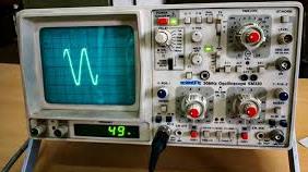
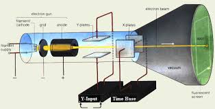
The cathode ray oscilloscope(CRO) is an electrical test device used to produce waveforms in response to several input signals. It was originally known as an oscillograph. The cathode ray oscilloscope is a development of the cathode ray tube. A standard cathode ray tube has the following parts:
The electron gun
A system of plates for deflecting the electron beam
An evacuated strong glass envelope
A fluorescent screen at one end of the glass envelope
Inside the cathode ray oscilloscope, the main parts are as shown.
we now discuss each of the components making the CRO.
cathode ray oscilloscope(CRO): The electron gun
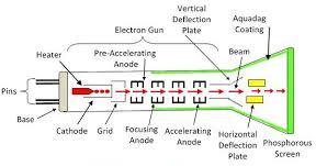
It is the component that supplies the electrons. After producing electrons, it accelerates them towards the screen and focus the beam to a point on the screen. The electron gun consists of :
a heated cathode
a grid to control electrons flow
anodes to accelerate and focus the electron beam
Each of the above parts is maintained with a direct current potential from E.H.T source and a potential divider as shown.
Electron gun in 2-DElectron gun in 3DA practical electron gun
Cathode is coated with thorium or strontium oxides .These which are preferred because they need little energy to extract electrons from them.
Anodes are made of cylinders and discs maintained at high positive potential relative to the cathode . This makes them able to attract the emitted electrons and direct them towards the screen.
Cathode ray oscilloscopes Anodes as focusing beam
Focusing the cathode beam involves using two anodes that are at different potentials.
consider the diagram below:
Anode A1 is at higher potential compared to anode A2. There is an electric field between the two anodes and there direction is such that to converge a diverging beam that is leaving the cathode through aperture of anode A1.
Electric field intensity increases when the potential difference between the two anodes A1 and A2. Increasing Electric field intensity increases the degree of focusing.
The potential difference is controlled by the potential divider P which is the focusing knob on the control panel.
The CRO grid
In cathode ray oscilloscope, grid is a small hollow cylinder with a small hole at the end. Grid is used to control the intensity of the beam. The figure below shows cathode ray illustrated in a cathode ray tube.
The potential divider is used to make the grid more negative or less negative. Sliding it to the left increases it’s negative potential and sliding it to the right reduces the negative potential. When the grid is made less negative, more electrons are allowed to pass through it and when it is more negatives, fewer electrons are allowed to pass through.
Because Intensity of the spot on the screen is determined by the by the number of electrons striking the screen, grid is therefore used to control the intensity of the beam and hence brightness of the spot on the screen. The brightness knob controls the potential divider that varies the potential difference between the grid and the cathode. see the diagram below:
The cathode ray oscilloscope deflection System
Deflection system is used to alter direction of the beam horizontally or vertically. If the deflection system is off or absent, the the beam will strike the screen at the center. The vertical deflection system causes the beam displaced up or down from the center of the screen. Horizontal deflection system displaces the beam on either sides of the center spot.
the cathode ray oscilloscope Vertical Deflection System
They causes the beam to deflect vertically across the screen when they are switched on. Vertical deflection system is also known as the Y-plates and their signal is usually fed in through the Y-Input terminal.
Consider the setup below:
When the switch is closed, Y1 is at positive potential while Y2 is at negative potential. The beam is therefore attracted towards plate Y1 and so the beam hits the screen at B.
If polarity is changed such that Y2 is the positive, bright spot is observed at point C on the screen. This shows that the beam has bent towards Y2 . If There is a constant reversal of the polarities of the vertical deflection system, the spot on the screen keeps shifting from B to C to B at the frequency of the reversals.
Most often, an a.c is connected to the vertical deflection system and so the spot is observed moving up and down according to frequency of the a.c voltage.
When the frequency of the a.c voltage is high, the persistence of vision makes the movement of the spot appear as a vertical straight line. The movement goes up and down on the screen. see the figure below:
cathode ray oscilloscope horizontal deflection system
They are also referred to as the X-plates as they cause the deflection of the spot to occur parallel to the X-axis.
consider the set up below:
When the plates are arranged as above, x1 is at positive potential. As a result, the electron beam is deflected horizontally towards M. When The polarity are changed such that x2 is now the positive one, the beam is deflected towards N.
A varying voltage is applied to the X-plates from a special circuit known as the time base. The time base circuit moves the bright spot at a constant speed. It travels from one end of the screen to the other. When it reaches the end, it disappears momentarily before it reappears again and moves across.
The moment the spot is moving across the screen is known as the sweep. The moment it is disappearing from the screen is known as the flyback
Consider the figure below.
Explaining the time base wave
When the time base circuit is switched on, the voltage increases uniformly to peak (sweep) and then drops suddenly(flyback).
Increase of voltage causes the bright spot to move horizontally at a uniform speed until a peak voltage is reached. The time base voltage then drops suddenly to a maximum negative value. This causes the spot to fly back to the starting point at the other end of the screen. The voltage builds up again and the process is repeated in cycles.
The movement of the spot across the screen (sweep) can be controlled using the time base control knob. This knob operates the frequency of the time base voltage. Increase of frequency results to reduction of sweep time. When the frequency is low, the spot moves slowly across the screen. You can follow it with your eye as shown in the diagram below.
When frequency of the time base is high, the movement of spot traces a permanent horizontal line across the screen as shown below.
If input voltage at the y-plates and the time base voltages are switched on simultaneously. The spot is deflected vertically and horizontally at the same time causing a two dimensional movement in form of a sine curve on the screen. The figure below illustrates the Y-plates and time base circuit.
In the figure, we are shown the signal that would be formed when the two circuits are working simultaneously.
The cathode ray oscilloscope (CRO) screen
It is usually coated with a fluorescent substance called phosphor. Phosphor, which is made from zinc sulphide glows when electrons collides with it. This glow persists for about 0.05 seconds and so the screen continues to glow even after the beam has passed the point of impact.
The persistence of the phosphor allows the waveform to be seen. Persistence of vision in the eye also enables this observation on the screen. Inside of the tube is coated with graphite because of the following functions:
conduction of the electrons to the earth
shielding the beam from external electric fields
Accelerating electrons towards the screen since it has the same potential as the anodes.
The following video shows how to use the cathode ray oscilloscope:
The term “properties of cathode rays” refers to the various physical characteristics and behaviors observed when cathode rays are studied under different conditions.
properties of cathode rays includes:
They travel in a straight line
causes fluoresce or glow to certain materials
they are charged
possesses kinetic energy
pass through thin materials demonstrating their ability to penetrate objects to varying degrees. This depends on the material’s density and the energy of the rays.
ionize gases
The charge-to-mass ratio of cathode rays (electrons) is relatively high. A property used to identify the electron and distinguish it from other particles.
Deflection by Magnetic Fields
Showing that cathode rays travels in a straight line
When an opaque object is placed between the screen and the cathode in the path of the cathode rays, a sharp shadow is cast on the screen.
Cathode rays causes certain substances to glow or fluoresce
Fluoresce materials are materials that glows when electromagnetic energies falls on them. such materials includes zinc sulphide, Fluorescein, Rhodamine, Coumarin, Acridine Orange and Quantum Dots.
when cathode rays falls on screen coated with the fluoresce materials, the fluoresce material glows.
showing that cathode rays are charged
Cathode rays are deflected by both magnetic and electric fields.
Inside the magnetic field, the cathode rays are deflected towards the positive plate showing that they are negatively charged. Remember that opposite charges attract while while same charges repel from the basic law of charges. see the figure below:
When cathode rays passes through magnetic field, they are deflected in the direction determined by Fleming’s left-hand rule. The deflection in magnetic field shows that they are negatively charged as shown in figure below.
Cathode rays have kinetic energy
The deflection of cathode rays in a magnetic field shows they are moving, and therefore possess kinetic energy. By measuring how much the cathode rays bend in the magnetic field, you can calculate their velocity. Using the velocity, you can compute the kinetic energy of the cathode rays.
When cathode rays are suddenly stopped by a metal target, they can produce x-rays. This confirms that they are actually a stream of fast moving electrons.
Exam Questions on properties of cathode rays
Figure 14 shows a cathode ray tube. A metal plate is placed between the anode and the screen.
(I) State with reason what would be observed on the screen when the cathode rays are produced. (2 marks)
(ii) State the effects on the cathode rays produced when the anode is increased. ( 2 marks)
Exam questions on Cathode rays are an important topic in physics and chemistry. They test knowledge on key curriculum areas that includes:
Atomic Structure
Electricity and Magnetism
Properties of Matter
Electron beams
Charge-to-mass ratio (e/m)
Millikan’s oil drop experiment
etc.
below are questions commonly tested in physics examinations on this topic;
1. The figure 1 below represents a cathode ray oscilloscope (C.R.O) (i) Name the parts labeled A and B (2 marks)
Figure 1
A.…….………………………………………………………………………………………… B.…….…………………………………………………………………………………………. ii) What are the functions of parts labeled C and D (2 marks) C ………………………………………………………………………………………………… D …………………………………………………………………………………………………. iii) Explain how electrons are produced. (1 mark) …………………………………………………………………………………………………… ……………………………………………………………………………………………………. iv) Give a reason why the tube is evacuated. (1 mark)
2. State the function of the grid in a cathode ray tube (CRT) (1 mark)
3. State two reasons why the CRO is a more accurate voltmeter than a moving coil voltmeter. (1 mark)
4. Figure 2 shows a cathode ray entering into a region between two charged plates.
Complete the diagram to show the path of the ray in the electric field. (1 Mark)
Contains information related to marketing campaigns of the user. These are shared with Google AdWords / Google Ads when the Google Ads and Google Analytics accounts are linked together.
90 days
__utma
ID used to identify users and sessions
2 years after last activity
__utmt
Used to monitor number of Google Analytics server requests
10 minutes
__utmb
Used to distinguish new sessions and visits. This cookie is set when the GA.js javascript library is loaded and there is no existing __utmb cookie. The cookie is updated every time data is sent to the Google Analytics server.
30 minutes after last activity
__utmc
Used only with old Urchin versions of Google Analytics and not with GA.js. Was used to distinguish between new sessions and visits at the end of a session.
End of session (browser)
__utmz
Contains information about the traffic source or campaign that directed user to the website. The cookie is set when the GA.js javascript is loaded and updated when data is sent to the Google Anaytics server
6 months after last activity
__utmv
Contains custom information set by the web developer via the _setCustomVar method in Google Analytics. This cookie is updated every time new data is sent to the Google Analytics server.
2 years after last activity
__utmx
Used to determine whether a user is included in an A / B or Multivariate test.
18 months
_ga
ID used to identify users
2 years
_gali
Used by Google Analytics to determine which links on a page are being clicked
30 seconds
_ga_
ID used to identify users
2 years
_gid
ID used to identify users for 24 hours after last activity
24 hours
_gat
Used to monitor number of Google Analytics server requests when using Google Tag Manager