Category: Physics

  • useful equations for transformers

    useful equations for transformers

    Useful equations for transformers relate voltage, current, and number of turns in the primary and secondary coils. In the equation, we assumes that the power we feed into the transformer is the same power given out. This assumption is based on another assumption that the coils of wire in the transformer is negligible.

    Electrical power = Current(I) x Voltage(V)

    power input from primary coil = Current in primary coil (Ip) x Voltage in primary coil(Vp)

    power output from secondary coil = Current in secondary(Is) x Voltage in secondary coil(Vs)

    For an ideal transformer that has no energy loss;

    Power input = power output

    that is: Ip x Vp = Is x Vs

    useful equations for transformers: The turn ratio

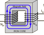
    From previous lessons, we learnt that the magnetic flux changes in the primary coil. This changing magnetic flux links with each turn in the secondary coil.

    transformer

    Total e.m.f in the secondary coil is the sum total of the e.m.f induced in each turn of wire in the secondary coil. The voltage produced in the secondary coil is proportional to the number of turns in that coil. The voltage changes as the number of turns changes. We show that, the secondary coil multiplies the voltage supplied from primary coil by a constant factor that is given by:

    $$\frac{\text{number of turns in secondary coil}(N_s)}{{\text{number of turns in primary coil}(N_p)}}$$

    From the above equation we can see that:

    $$\frac{\text{Secondary voltage}(V_s)}{\text{primary voltage}(V_p)} =\frac{\text{Number of turns in secondary voltage}(N_s)}{\text{Number of turns in primary voltage}(N_p)}$$

    in short form;

    $$\frac{(V_s)}{(V_p)} =\frac{(N_s)}{(N_p)}$$

    The above equation is know as the turns rule and helps determine voltage produced by a transformer.

    The useful equations for transformers

    From the equation :

    $$I_p \times \ V_p = I_s \ \times \ V_s$$

    we can obtain by rearranging the equation:

    $$\frac{I_p}{I_s} = \frac{V_s}{V_p}$$

    combining this with the turns rule equation we have:

    $$\frac{I_p}{I_s} = \frac{V_s}{V_p} = \frac{N_s}{N_p}$$

    Example 2 problems: useful equations for transformers

    A transformer is used to provide power to a 10 V lamp from an a.c mains supply of 240 V. What should be the number of turns of the secondary coil if primary coil has 1800 turns.

    solution to the problem

    This is a case of step-down transformer. The voltage from the mains needs to be reduced to 10 V needed by the lamp.

    $$\frac{V_s}{V_p} = \frac{N_s}{N_p}$$ $$hence$$ $$\frac{10}{240} = \frac{N_s}{1800}$$ $$\text{therefore:} N_s=\frac{10}{240} \ \times 1800 = 75 \ turns$$

    Example problem 2

    A power station has an output of 45KΩ at a potential difference of 10 Kv. A transformer with a primary coil of 2000 turns is used to step up the voltage to 140Kv for transmission. Assuming that there is no power losses in the transformer, calculate:

    (a) current in the primary coil

    (b) number of turns of the secondary coil

    (c) current in the secondary coil

    Example problem 3

    A power station has an output of 50Kw at a potential difference of 1000V. The voltage is stepped up to 30000Kv by transformer T1 for a transmission along a grid of resistance 2500 Ω and then stepped down to a voltage of 240V by transformer T2 at the end of grid for use in a home.

    (a) Given that the efficiency of T1 is 95% while that if T2 is 90%, find:

    (i) The power output of T1

    (ii) current in the grid

    (iii) Power loss in the grid

    (vi) input voltage of T2

    (v) the maximum power and current available for use in the home

    (b) Explain the purpose of stepping up the voltage at the power station

    Related topics


  • Exam questions on current and electricity

    Exam questions on current and electricity

    Current and electricity are core topics in physics, encompassing electric current, circuits, resistance, and the behavior of electrons. Key areas that can be tested include the nature of electric current. Another key area is Ohm’s law, Series and parallel circuits, the heating effect of electric current among others

    Questions

    1. Figure 1 shows four identical bulbs connected to a 15 volt battery whose internal is negligible.
    Diagram for Exam questions on current and electricity. Question one
    Figure 1

    Determine the reading of the voltmeter V. (2 marks).

    2. Figure 14 shows a circuit in which a battery. a switch , a bulb, resistor P, a variable resistor Q. a voltmeter V and two ammeters A1 and A2 of negligible resistance are connected.

    P has a resistance of 10 Ω. When the switch is closed A1 and A2 reads 0.10 A and the voltmeter reads 1.5 V.

    (a) Determine;. 
    (i) the current passing through P; (3 marks).
    ----------------------------------------------------------------------------------------------------------------------------------------------------------------------------------------------------------------------------------------------------------------------------------------------------------------------------------------------------------------------------------
    (ii) the resistance of the bulb (2 marks).
    ----------------------------------------------------------------------------------------------------------------------------------------------------------------------------------------------------------------------------------------------------------------------------------------------------------------------------------------------------------------------------------
    (b) The variable resistor Q is now adjusted so that a larger current flows through A2 .
    (i) State how this will affect the resistance of the bulb (1 mark)
    ----------------------------------------------------------------------------------------------------------------------------------------------------

    (ii) Explain your answer in (b)(i). (3 marks)
    ------------------------------------------------------------------------.
    ------------------------------------------------------------------------.
    ------------------------------------------------------------------------.
    ------------------------------------------------------------------------.
    ------------------------------------------------------------------------.
    ------------------------------------------------------------------------.
    ------------------------------------------------------------------------.

    (c) A house has one 100W bulb, two 60W bulbs and one 30W bulb. Determine the cost of having all the bulbs switched on for 70 hours,. given that the cost of electricity is 40 cents per kilowatt hour. (3 marks).
    • 3. (a) Define current stating its S.I units.               (2 mark)
    ------------------------------------------------------------------------------------------------------------------------------------------------------------------------------------------------------------------------------
     (b) A battery circulates charges round a circuit for 1.5 minutes. If the current is held at 2.5 Amperes,   what quantity of charge passes though the wire? (2 marks)
    ------------------------------------------------------------------------------------------------------------------------------------------------------------------------------------------------------------------------------

    4. Figure 2 shows arrangement of three capacities of 10µF, 2µF and 5µF.

     network three capacities of 10µF, 2µF and 5µF and a cell of 2V

    Determine the effective capacitance. (3 marks)

    5.(a) Figure 8 shows a graph of potential difference V (volts) against a current I(amperes) for a certain device.

    From the graph:

    (i) State with a reason whether or not the device obeys ohms law.    (2 marks)

    (ii) determine the resistance of the device at ;

         (I) I =1.5 A           (2 marks)

          (II) I = 3.5 A         (2 marks)

    (iii) From the results obtained in (ii) state how the resistance of the device varies as the current increases.      ( 1 mark)

    (iv) State the cause of this variation in resistance.  (1 mark)

    5(b) Three identical dry cells each of e.m.f 1.6 V are connected in series to a resistor of  11.4 ohms.  A current of 0.32A flows in the circuit. Determine:

       (i) The total e.m.f of the cells     (1 mark)

      (ii) The internal resistance of each cell;    (3 marks)

    6. Figure 6 below shows an electric generator. The points P and Q are connected to a cathode ray oscilloscope (CRO).

    Figure 6

    Sketch on the axes provided the graph of the voltage output as seen on the CRO, given that when t=0 the coil is at the position shown in the figure.   (2 marks).

    7. A 60 W bulb is used continuously for 36 hours. Determine the energy consumed. Give your answer in kilowatt hour (kWh).  (3 marks)

    8. Figure 8 shows the cross-section of a dry cell. Use the information on the figure to answer questions 4 and 5.

    Figure 8

    Name the parts labelled A and B. (2 marks)

    8 (b)  State the use of the manganese(IV) oxide in the cell. (1 mark).

    9. A 4 ohms resistor is connected in series to a battery of e.m.f 6.0 V and negligible internal . Determine the power dissipated by the resistor (2 marks)

    10. State the reason why electrical power is transmitted over long distances at very high voltages .(1 mark)

    Related pages

  • Electric current and potential difference

    Electric current and potential difference

    Electric current and potential difference represents two phenomenon that depends on each other to exist in electricity concepts. An electric current is the rate of flow of charge through a conductor. Current flows when there is a potential difference between two points in a conductor. Electric current is measured in amperes by an instrument called ammeter. An ammeter is an electrical instrument used to measure the current flowing through a circuit. The ammeter is designed to be connected in series with the circuit. This ensures that the current flows through the ammeter, allowing it to accurately measure the amount of electrical current.

    There are two types of ammeters:

    Instruments used in experiments of electric current and potential difference

    • Analog Ammeter: This uses a needle or pointer to indicate the current on a scale.

    The figure below shows an analog ammeter ammeter common in school laboratories.

    An ammeter to measure Electric current
    An ammeter

    2. Digital Ammeter: This displays the current measurement on a digital screen. It provides a digital readout of the electrical current. Digital ammeter allows one to choose a scale of measurement in amperes (A), milli-amperes (mA), or micro-amperes (µA). It uses a numerical display rather than a moving needle or pointer.

    A Digital ammeter

    Electric current flows between two points in a closed path due to a potential difference between those two points. Sometimes the flowing current can be too small to me measured by an ammeter. A more sensitive instrument may therefore be required to measure small currents.

    A millimeter is an instrument used to measure current in terms of one in thousand of an ampere. A milliammeter measures current in terms of milli-amperes.

    $$1 \ milli-ampere(MA) = \frac{1}{1000} Amperes$$

    Much smaller currents can be measured by a micro- ammeter. A micro-ammeter measures current in terms of micro-ampere.

    $$1 \ micro-ampere(\mu A)= \frac{1}{1000000} \ amperes $$

    experiments of electric current and potential difference: A micro-ammeter to measure very small electric currents and a milli-ammeter to measure relatively small currents.
    A micro-ammeter

    Using an ammeter in measuring electric current

    An ammeter has very low electrical resistance. Therefore it is connected in series with the instrument whose current passing through need to be measured. When connecting an ammeter in the circuit, ensure it is done correctly. The correct procedure is such that current enters the ammeter through positive terminal and exits through the negative terminal. If connected such that convectional current enters through negative terminal, the ammeter may get damaged.

    The figure below shows the ammeter connected in series with the bulb. The convectional current flowing through the bulb also flows through the ammeter.

    Ammeter connected in series with a bulb in experiments of electric current and potential difference
    correct ammeter connection

    The figure below shows wrong ammeter connection. Note that the positive terminal of the ammeter is connected to the negative terminal of the cell.

    wrong ammeter connection

    Before connecting the ammeter in a circuit, confirm that it’s pointer is at zero mark on the scale. Otherwise, use the zero adjusting screw to move it to the correct position. Most of ammeters has two scales. An appropriate scale should be selected to safeguard the coil from damaged if current passing exceeds its capacity. For example an ammeter can have a scale of (0-3)A or (0-5)A. The figure below shows an ammeter dashboard with two scales; (0-5)A and (0-2.5)A.

    Ammeter reading with two scales

    If a scale of (0 – 5) A is selected, the meter can read up to 5 A. With such a scale, 10 divisions represents 1.0 A. For a (0-2.5) A scale, ten divisions will represent 0.5 A meaning each division is 0.05 A. From the diagram, the reading on the ammeter is 2.45 A while reading (0-5) A or 1.225 while reading the (0 -2.5) A.

    Electric current and potential difference: using a voltmeter

    while investigating electric current and potential difference, we need to measure potential difference across various components in the circuit. A voltmeter is always connected across the device (parallel to the device) which the voltage is to be measured. The figure below shows voltmeter connected across the bulb in parallel arrangement.

    circuit diagrams showing how to connect voltmeter while measuring potential difference across the bulb

    Voltmeter is connected in series because it is an instrument with high resistance to the flow of current. Therefore, It takes no current from the component across which the voltage is to be measured.

    The positive terminal of the voltmeter is connected to the point where convectional current is entering a component. Its negative terminal is connected to the point where the current is leaving the component.

    One should ensure that the pointer is exactly on the zero mark before connecting the voltmeter. If pointer is not at zero, the pointer should be adjusted to zero by the screw.

    Related Topics


  • Examination Questions on measurements

    Examination Questions on measurements

    Examination questions on measurements basically covers concepts like:

    •  Length and Distance
    • Weight and Mass
    • Basic Units and Conversions
    •  Volume and Capacity
    • Time
    • Temperature
    • Derived Units and Calculations
    •  Measuring Instruments
    • Precision and Accuracy

    Here are the questions that involves measurements

    1. The diagram below shows a piece of wood whose length is being measured using a strip of           measuring tape.


                What is the length of the piece of wood.

    2. Figure 1 below shows a Vernier calipers being used to measure the thickness of an object. It has a error of +0.01 cm.

    What is the correct measurement?                                                                       (2 marks)

    3. Figure  below shows  Perspex  container  with a square base  of side  5 cm . It is carrying  water  to a height  of 7 cm.

    When pebble is immersed  into  the water, the level  rise  to 10 cm. what is  the volume of the pebble? (2 marks)

    4.   A  drop  of  oil volume  6 x 10 -9 m3 forms  a patch  of area  0.0755 m2  on a water  surface. Estimate the of an oil  molecule ( 2 marks).

    Related topics

  • Exam questions on thin lenses

    Exam questions on thin lenses

    Exam questions on thin lenses often cover the properties of converging (convex) and diverging (concave) lenses. These questions include topics like image formation, focal length, magnification, and the thin lens equation. 

    You face questions asking you to define key terms. They ask you to distinguish between real and virtual images. You can also be asked to apply the thin lens formula to calculate image distances, focal lengths, or magnification. Additionally, questions involve ray diagrams, understanding how lenses correct vision defects, or comparing lenses with mirrors. 

    Here’s a breakdown of common question types:

    • Definitions and Concepts
    • Image Formation
    • Thin Lens Equation and Calculations
    • Applications and Comparisons
    • higher order questions live derivation of equation

    Examination Questions on thin lenses

    1. Figure 10 below shows an object in front of a lens.

    (i) Using rays locate the image of the object as seen by observer E.

    (ii)Give one application of such a lens as used above.

    (iii) Write three similarities between an eye and a camera

    ( b)   Figure 11 (a) and (b) show diagram the human eye

    In figure 11 (a) sketch array diagram showing long sightedness

    And In figure 11 (b) sketch array diagram showing how a lens is used to correct the long sightedness.

    (c) A object of height 10.5 cm stands before a diverging lens of focal length 20 cm and a distance of 10cm from the lens. Find.

    i)          Image distance

    ii)         Height of the image

    iii)        Magnification

    2. A real object of height 1 cm placed 50 mm from a converging lens. It forms a virtual image 100 mm from the lens.

    (i) Determine the:

    (I) focal length of the lens ; (3 marks)

    (II) magnification. (2 marks)

    (ii) On the grid provided, draw to scale the ray diagram for the setup to show how the image is formed (3 marks)

    3. Figure 8 shows an object O placed in front of a diverging lens whose principal focus is F.

    Figure 8

    on the figure , draw a ray diagram to locate the image formed (3 marks)

    Question 4

    17 (a) Figure 16 shows a graph of magnification against object distance for an object placed in front of a lens of focal length 20 cm.

    Using the graph;

    (i) State the effect on the size of the image when the object distance is increased from 25 cm. (1 mark)

    (ii) Determine the distance between the object and the lens when the image is the same size as the object (2 marks)

    (iii) Determine the image distance when the object distance is 25 cm. (3 marks)

    Related topics

  • Trigonometric ratios:-Table of tangents

    Trigonometric ratios:-Table of tangents

    The table of tangents holds values for every acute angle from 0o to 90o. Each angle has a unique tangent ratio. We get this ratio when two lines meet to make the angle.

    Every combination of opposite and adjacent lines that makes a right angled triangle has a unique angle which they make.

    If we know the acute angle in a right angled triangle, we can use tables of tangents. This helps us find its corresponding tangent ratio. Similarly, if we know the angle and just one side, we can find the angle’s ratio. Then, we use the tangent relationship to find the other side.

    The table of tangents consists of angles from 0o to 90o. We express these angles in 4 significant figures and record their values in a table. All we need to do as mathematician is get a certain angle and find it’s corresponding ratio from the tables.

    We expresses angles in the table of tangents in degrees, points of degrees and as well as in minutes. 1 degree (1o) is equivalent to 60 minutes(60′).

    We have divided the table of tangents into three major columns as shown in the table extract below:

    The first column represents whole number degrees from 0o to 90o  and has column head labeled xo which represents

    The second column consists of 0.0o to 0.9o which divides a degree into 10 smaller units hence giving an accuracy of 0.1o.

    The third column is the one we have labeled ADD and it provides the second decimal value of the angle. Using the table of tangents, we can find angles u to second decimal places.

    Example

    Determine the tangent of 36.57o

    solution

    In the column labelled xo , look for the row headed 36 and then move along this row until you reach 0.5. The number at the intersection of 36 and 0.5 is 0.7400

    note that the number is recorded as 7400 and not 0.7400. This is done to save on space but you should check the first column after 36, That is, column headed 0.0, whatever value that is stated on that row in that column should be used as the starting value for all the columns in that row.

    so tan 36.5 =0.7400, to get the value for tan 36.57, we go to the add column and check on the column 0.07 and add it’s value on the far right of our previous value we read from the table. In this case it is 19 and should be read as 0.0019

    hence tan 36.57 should be 0.7400+0.0019 = 0.7419

    Example

    Use tables to find the tangent of 77o48′

    solution

    1o=60′, hence 48′ = (48′ x 1o)/60′ = 0.8o

    then 77o48′ can be expressed as 77.8o

    From the tables, you identify row 77 at xo column then move up to to the column 0.8 and read off that value at the intersection. This value is 0.6252 hence tan 77o48′ = tan 77.8o = 0.6252

    Example

    Find angle θ and α in the figure below.

    Related Topics


  • Exam questions on waves

    Here are exam questions on waves that are common in national exams.

    1. State two differences between electromagnetic waves and mechanical waves (2 marks)
    2. Figure 3 show straight waves incident on a divergent lens placed in a ripple tank to reduce its depth.
    showing exam question diagram on refraction of waves

    Complete the diagram to show the waves in both the shallow region and beyond the lens (2 marks)

    3. A ship in an ocean sends out an ultra sound whose echo is received after 3 seconds. if the wavelength of the ultra sound in water is 7.5 cm and the frequency of the transmitter is 20 kHz, determine the depth of the ocean. (3 marks)

    4. Explain the fact that radiant heat from the sun penetrates a glass sheet while radian heat from burning wood is cut off by the glass sheet. (2 marks)

    Question 5

    5. (a) figure 5 shows a displacement-time graph for a progressive wave.

    displacement time graph for a wave profile on exam  questions on waves
    figure 5

    (i) State the amplitude of the wave (1 mark)

    (ii)Determine the frequency of the wave (4 marks)

    (iii) Given that the velocity of the wave is 20 ms-1 , determine it’s wavelength. (3 marks)

    (b)Figure 6 shows two identical dippers A and B vibrating in water in phase with each other . The dippers have the same constant frequency and amplitude. The waves produced are observed along the line MN:

    Figure 6

    It is observed that the amplitude are maximum at points Q and S and minimum at points P and R.

    (i) Explain why the amplitude is maximum at Q. (2 marks)

    (ii) state why the amplitude is minimum at R (1 mark)

    (iii) State what would have happen if the two dippers had different frequencies . ( 1 mark)

    6. Figure 7 shows water waves incident on a shallow region of the shape shown with dotted line.

    Figure 7

    On the same diagram, sketch the wave pattern in and beyond the shallow region (1 mark)

    7 . Figure 7 shows standing wave on a string. It is drawn to a scale of 1:5

    Figure 7

    (a) Indicate on the diagram the wavelength of the standing wave (1 mark)

    (b) Determine the wavelength of the wave. (1 mark)

    Related topics

  • Exam questions on electromagnetic induction

    Exam questions on electromagnetic induction

    1. Figure 15 shows two coils A and B placed close to each other. A is connected to a steady D.C supply and a switch, B is connected to a sensitive galvanometer.
    shows two coils A and B placed close to each other
    Figure 15

    (i) The switch is closed . State the observations made on the galvanometer (2 marks)

    (ii) Explain what would be observed if the switch is then opened. (2 marks).

    2. The primary coil of a transformer has 1000 turns and the secondary coil has 200 turns. The primary coil is connected to a 240V a.c mains, supply.

    (i) Explain how an e.m.f is induced in the secondary coil (2 marks)

    (ii) Determine the secondary voltage (3 marks)

    (iii) Determine the efficiency of the transformer given that the current in the primary coil is 0.20 A and in the secondary coil it is 0.80 A

    Question 3

    3 .(a)(I) State Faraday’s law of electromagnetic induction (1 mark)

    (ii) State the Lenz’s law of electromagnetic induction (1 mark)

    (b) A transformer is used on a 240 a.c supply to deliver a 7.5 A at 90 V to a heating coil. if the transformer is 95% efficient, what is the current in the primary winding? (2 marks).

    ( c) Hysteresis losses are a source of inefficiency in a transformer. explain

    (I) What is meant by hysteresis losses (2 marks)

    (ii) How these hysteresis losses can be minimized. (1 mark)

    ( d) An a.c supply lights a lamp with the same brightness as a 12 V battery. Determine

    (i)The r.m.s voltage (1 mark)

    (ii) The peak voltage of the a.c supply (2 marks)

    Question 4

    4. (a) State the lenz’s law (1 mark)

    (b) The diagram in figure 7 below shows a coil of wire next to a magnet. A voltmeter is connected to the coil of the wire.

    A coil next to a magnet

    Describe two ways of inducing a voltage in the coil of the wire. (2 marks)

    (c) State the three factors that affects the size of the induced voltage (3 marks)

    (d) A 6v, 24w lamp shines at a full brightness when it is connected to the output of a mains transformer as shown in figure 8 below.

    Assuming that the transformer is ideal, calculate

    (i) The number of turns in the secondary coil if the lamp is to work at it’s normal brightness (2 marks)

    (ii) The current which flows in the mains cables (2 marks)

    Question 5

    5. Figure 14 shows an E shaped steel block being magnetised by a current through two coils in series.

    on the figure, indicate

    (i) the north and south poles of the resulting magnet (1 mark)

    (ii) the complete magnetic field pattern between the poles (1 mark)

    (b) Figure 15 shows the permanent magnet made in part (a) above

    Figure 15

    A coil wound loosely on the middle limb is connected in series with low voltage a.c and a switch. State and explain the observations made on the coil when the switch is closed (2 marks)

    Question 6

    6.A piece of metal AB was magnetised using the method shown below.

    (a) By what method is metal AB being magnetised? (1 mark)

    (b) what is the polarity of end B (1 mark)

    Question 7

    7. Figure 2 shows a soft iron bar AB placed in a coil near a freely suspended magnet.

    Explain the observation made when the switch is closed (2 marks)

    Question 8

    8. When a transformer is connected to an ac source, the output voltage is found to be 24 V. If the power input is 200 W, determine the output current. (assume the transformer is 100% efficient). (3 marks)

    9. (a) State what is meant by the term “electromagnetic induction”.    (1 mark).

    9 (b) Figure 9, shows a simple electric generator.

    (i) Name the parts labelled P and Q.      (2 marks)

    P ……………………………………………

    Q …………………………………………..

    (ii) Sketch on the axes provided a graph to show how the magnitude of the potential difference across R, changes with time t.  (1 mark)

    (iii) State two ways in which the potential difference produced by such a generator can be increased.    (2 marks)

    (c) In a transformer, the ratio of primary turns to the secondary turns is 1:10. A current of 500mA flows through a 200 ohms resistor in the secondary circuit. Assuming that the transformer is 100% efficient, determine:

    (i) the secondary Voltage; (1 mark)

    (ii) the primary voltage;    (2 marks)

    (iii) the primary current.     (2 marks)

    Related topics

  • Mutual Induction in coils

    Mutual Induction in coils

    Mutual induction is when current is induced in a coil due to changing magnetic flux of a second coil nearby. The changing magnetic flux in the first coil links with the second coil inducing an e.m.f in it.

    Demonstrating mutual induction

    The figure below consists of two coils P and S , battery, a. c power source, rheostat, galvanometer and switch connected as shown.

    When we close the switch K, the point on the galvanometer in the second coil deflects in one direction. It then returns to zero. When we open the switch, the pointer deflects to the opposite direction before falling back to zero. when we increase the primary current, more deflection is noted in either direction. If we replace a d.c source with an a.c power source , the pointer vibrates about point zero.

    Explaining the observations on the demo

    When we closed the switch, current in the primary coil increases from zero to maximum within a short time. As the current builds up, magnetic flux in the primary coil increases from zero to its maximum value. This change links with the secondary coil inducing an e.m.f in the secondary coil.

    Deflection of the galvanometer indicates that current is flowing in the secondary coil where it is connected. The current flow is momentarily. It flows once and stops. This is because the induced e.m.f in the secondary coil is momentarily . It happens when the current in the primary coil is building up from zero to maximum. When the current reaches the maximum value, the magnetic flux stops changing in the primary coil. Therefore, there is no further induction in the primary coil.

    Opening the switch causes the primary current to decay from maximum to zero. This happens in a very short time. Consecutively, magnetic flux in the primary coil linking with the secondary coil falls from maximum to zero. This causes changing magnetic flux in the primary coil that induces an e.m.f in the secondary coil.

    Induced e.m.f due to current decay

    We observes more deflection when switch is opened than when the switch is being closed. This shows that the induced e.m.f in the secondary coil is much higher when switch is opened than when it is closed. The reason behind this is that current in the circuit takes much shorter time to decay than to build up.

    Increasing current in the primary coil causes deflection on the galvanometer. This indicates that increasing current in primary coil causes changing magnetic flux in that coil hence continued induction of e.m.f in the secondary coil.

    Continuously decreasing current in the primary coil causes an e.m.f in the secondary coil due to decreasing magnetic flux linking with the secondary coil.

    From the Lenz’s law; the direction of the induced current when current is building up is as indicated in the diagram below:

    when the current is decaying, the direction of current according to Len’z law is as shown.

    Increasing efficiency in mutual induction

    The induced e.m.f in the secondary coil can be increased by winding the primary and secondary coils on a soft iron rod. The soft iron concentrates magnetic flux in both coils. See the figure below.

    A more efficient way of linking magnetic flux between the two coils is by winding the two coils on a soft iron ring as shown.

    More induced e.m.f can be attained by having more turns in the secondary coil. The e.m.f is induced in each turn of the secondary coil. This occurs because the magnetic flux of the primary coil links with each of the turns. The total e.m.f is thus the summation of the individual e.m.f from each turn.

    Related topics


  • GRADE Nine (9) TO SENIOR SCHOOL SELECTION FORM

    GRADE Nine (9) TO SENIOR SCHOOL SELECTION FORM

    The Grade 9 to Senior School selection process in Kenya involves students choosing their preferred pathways. They also choose subject combinations and schools. This is done through an online system managed by the Ministry of Education. 

    This process is part of the transition to Senior School under the Competency-Based Education (CBE) framework. Students will select their pathways and subject combinations and they will also choose up to 12 schools across four clusters. STEM is a mandatory pathway.

    SELECTION OF PATHWAYS AND SENIOR SCHOOLS

    • Determination of pathways per senior school
    • Determination of vacancies for boarding and day schooling in senior schools
    • Selection of pathways, subjects’ combination and schools by grade 9 learners

    Selection based on pathway

    The learner will select 12 schools for their chosen pathway as follows.

    • 4 schools in first choice track and subject combination
    • Four (4) schools in second choice subject combination
    • Four (4) schools in third choice subject combination (Total 12 schools)

    Selection based on accommodation

    Out of the 12 schools selected based on pathway:

    • 9 will be boarding schools; 3 from the learners’ home county, 6 from outside their home
      county/county of residence.
    • Three (3) day schools in their home sub county/sub county of residence. (Total 12 schools)
      Pre selection – A school that does not allow open placement can apply to be pre-select if it meets the criteria defined by the Ministry of Education.

    Accommodation- Based Breakdown

    Top 6 learners per gender in each STEM track per sub-county will be placed for Boarding in
    schools of choice

    • Top 3 learners per gender in each Social Science track per sub-county will be placed for
      Boarding in schools of choice
    • Top 2 learners per gender in each Arts and Sports Science track per sub-county be placed to
      Boarding schools of their choice
    • Placement of Candidates with Achievement Level of averaging 7 and 8 per track to boarding
      schools of their choice

    To get the form, click below:

    GRADE 9 TO SENIOR SCHOOL SELECTION FORM

    LEANER’S FULL NAME__________________________________________________

    ASSESSMENT NUMBER (KPSEA) __________________________________________

    DATE OF BIRTH____________________________GENDER ([] Male [] Female)

    CURRENT School NAME:_________________________________________________

    COUNTY OF Residence: _______________Sub-County of Residence_________________

    Parent/Guardian Name__________________________________________________

    Parent/Guardian Phone Number _____________________ID No___________________

    B. Selected Pathway & Subject Track

    [] STEM (Science, Tech, Eng., Math) __________________________________________

    [] Social Sciences______________________________________________________

    [] Arts & Sports Science__________________________________________________

     C. School Choices – Based on Pathways

        First choice (4 schools):

    1. School Name & County_______________________________________________
    2. School Name & County_______________________________________________
    3. School Name & County _______________________________________________
    4. School Name & County________________________________________________

     Second choice (4 schools):

    1. School Name & County________________________________________________
    2. School Name & County________________________________________________
    3. School Name & County_______________________________________________
    4. School Name & County________________________________________________

         Third choice (4 schools):

    • School Name & County _______________________________________________
    • School Name & County _______________________________________________
    • School Name & County _______________________________________________
    • School Name & County _______________________________________________

       D. Accommodation- Based Breakdown

           [] 3 Boarding Schools within home county

          [] 6 Boarding Schools outside home county

          [] 3 Day schools in home sub-county

    E. Teacher’s recommendation

    ___________________________________________________________________ ____________________________________________________________________________________________________________________________________________________________________________________________________________

     F. Learner’s Signature

                   Signature_________________________Date____________________________

     G. Parent/Guardian Consent

     I confirm that the above choices were made in consultations with the learner and based on MoE  guidance.

       Name_______________________________________________________

        Signature________________________ Date _________________________

    Download Microsoft word format free

    Related topics