The Fundamental Theorem of Calculus establishes a crucial link between differentiation and integration.
It essentially states that these two operations are inverses of each other, and it provides a way to evaluate definite integrals using anti-derivatives.
Suppose that f is continuous at a closed interval [a, b] . If the function F is defined on a closed interval [a, b] by:
$$F(x) = \int_{a}^{x} f(t) dt $$
where a is a real number, Then F is the anti-derivative of f. in other words, F'(x) = f(x)
consider the relationships:
then
f(x) = x2and
Note: We use the dummy variable (t) in the integrand to avoid confusion with the upper limit x.
Sometimes the fundamental theorem of calculus is interpreted to mean that:
differentiation and integration are inverse processes to each other.
It follows that:
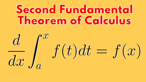
The fundamental theorem of calculus states that:
if f is continous on an open interval containing a and x and then we first integrate the function f and then differentiate with respect to x, then the result we get is the function f again.
In other words, the fundamental theorem of calculus argues that differentiation cancels the effect of intergration of continous f(x’).
in short:
For example
Example problem1
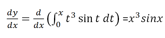
Use the fundamental theorem of calculus to find derivative of the following functions
(a)
solution
NOTE: The best way to benefit from this examples is trying the problem first before looking for answers and attempting again after checking your work against the answer.
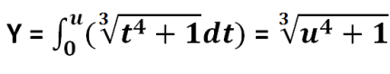
Example problem2
(b)
solution to problem 2
Example problem 3
Find h'(x) given that :
solution
let y=h(x) and u=x2 and hence:
since u=x2;
and therefore:
By use of chain rule:
which implies u3sinu(2x) = (x2)3sin(x2)2x resulting to:
=2x7sin(x2)
Example problem 4
Consider the expression below, we exchange the limits in the intergral and then change the sign from positive to negative before using the fundamental theorem to solve it.
Example problems on fundamental theorem of calculus
We exchange limits and so the sign of the integral so that the upper limit is the valuable x.
Example problem 6
Use the fundamental theorem of calculus to solve:
Solution
splitting the integral about point zero we have:
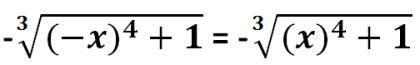
and then exchanging limits in the first integral;
let u=-x; first part of the expression above becomes;
from laws of differentiation du/dx=-1 and using chain rule;
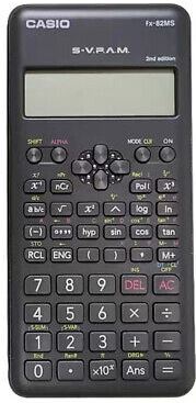
The most common calculator used by high school learners is ms fx-82 model. Calculator has many scientific functions that can help a student work out many scientific computations. However, ms fx-82 calculator is non-programmable.
Casio fx-82MS Scientific Calculator
The Casio fx-82 MS is a widely used scientific calculator. It is especially favored by students and professionals for its reliability. It also complies with exam requirements.
Key Features of fx-82 calculator:
240 Functions: Includes trigonometric, statistical, fractional, and exponential calculations.
Natural Textbook Display: Shows expressions as they appear in textbooks for easy comprehension.
Two-Line Display: Simultaneously displays input and output for clarity.
Multi-Replay Function: Allows quick recall and editing of previous formulas.
STAT-Data Editor: Supports mean, standard deviation, and regression analysis.
9 Variable Memories: Stores and recalls up to 9 data sets for efficiency.
Durable Design: Features robust plastic keys and a protective slide-on hard case.
Battery Powered: Operates on a single AAA battery.
Non-Programmable: Compliant with exam standards for academic use.
Portable and Lightweight: Compact design for easy everyday use.
Handling Precautions
Even if the calculator is operating normally, replace the battery at least after every two years. Continued use after the specified number of years can result to abnormal operation.
You should replace the battery immediately after display figures become dim.
A dead battery can leak, causing damage to and malfunction of the calculator. Never leave a dead battery in the calculator.
The battery that comes with the calculator is for factory testing, and it discharges slightly during shipment and storage. Because of these reasons, its battery life can be shorter than normal. For that reason, consider replacing the battery sooner.
Avoid use and storage of the calculator in areas subjected to temperature extremes, and large amounts of humidity and dust.
Do not subject the calculator to excessive impact, pressure, or bending.
Never try to take the calculator apart.
Use a soft, dry cloth to clean the exterior of the calculator
Do not use a nickel-based primary battery with this product.
use of incompatible batteries such as nickel-based primary battery with fx-82ms calculator can result in shorter battery life and product malfunctioning.
press 2 and the use > and < to adjust display contrast. when satisfied with the display settings, press AC button
use of calculator keys
To use the alternate function of a key, press [SHIFT] key followed by the key. The alternate function is indicated by the text printed above the key. The alternate function is usually marked with a different color from the main key.
Basic operations in calculator
use AC button to clear all values.
To clear memory press shift then mode . Three screens will display as follow:
The amount of current produced from changing magnetic flux depends on a number of factors which includes:
Rate of change of magnetic flux
strength of magnetic field
number of turns in a coil
i. Rate of change of magnetic flux
The faster the rate of change of magnetic field, the higher the magnitude of the induced current.
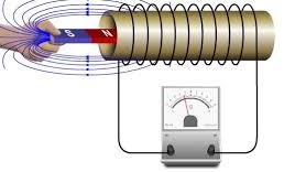
Consider a coil of about 200 turns of a wire, sensitive galvanometer and a magnet arranged as shown in figure below.
To investigate how rate of change of magnetic flux, you move the magnet towards the coil and away at various speeds such as very fast, moderately fast and slowly.
Advertisement
You observe that the faster the magnet is moved to and from the coil, the higher the deflection on the galvanometer. This shows that induced EMF is highest when the rate of change of magnetic flux is highest.
Magnetic flux could be interpreted as the number of magnetic field touching the coil at any given moment.
Explanations
Magnetic flux Φ is the strength of magnetic field threading a given area.
The magnetic flux Φ changes when the magnet is withdrawn from the coil where a faster withdrawal gives rise to a higher rate of change in magnetic flux linking the coil which then gives an increased induced Electromotive force(e.m.f)
see the diagram below that shows magnetic field lines:
ii. strength of magnetic field
Moving a stronger magnetic towards or away from the coil causes increase of the induced current when the speed of movement remains constant.
Consider a u-shaped electromagnet and a variable resistor connected to a circuit shown such that an electromagnet can have it’s strength varied by changing current passing through using the variable resistor.
After the setup, you can do the following to investigate the current induced with strength of the magnet:
Adjust the variable resistor so that minimum current flows.
Move the conductor PQ in a direction perpendicular to the magnetic field of the electromagnet and note deflection on the galvanometer.
change values of current and record corresponding readings on the galvanometer when wire cuts across the magnetic field.
Observations
Whenever current through the ammeter is increased, a greater deflection is obtained on the galvanometer when the conductor wire cuts across the magnetic field.
Explanations
Higher current passing through a coil of wire leads to a stronger electromagnet that will produce stronger magnetic field .
We can therefore conclude that the magnitude of the induced current is directly proportional to the strength of the magnetic field from which it is being produced.
iii. number of turns in a coil
If all other factors are held constant but the number of turns of wire on the coil increased, the induced current is observed to increase proportionately to increased number of turns.
Advertisement
Having at your disposal insulated copper wire, sensitive galvanometer, magnet and connecting cables, you make a coil of numbered turns of wire and set up the apparatus as shown
to investigate how number of turns in a coil affects magnitude of the induced emf, do the following:
Insert a magnet in the coil and then withdraw it at a steady speed and then observe and record the maximum reading on the galvanometer.
Increase number of turns on the coil at equal intervals says 50, 100,150,200,250 etc and repeat the above procedure noting the maximum deflection each time.
Observations
Each time the number of turns of the coil is increased and all other factors held constant, a higher deflection on the galvanometer is recorded. The deflection is proportional to the number of turns used.
Explanations
Increased deflection indicates more current is produced in the coil. The induced emf is proportional to the number of turns and so we can say that each turn on the coil induces it’s own e.m.f. The total induced e.m.f is therefore a summation of all emfs produced by individual turns.
Infact by application of calculus, we can be able to express summation mathematically, but we will do that later in more advanced lessons.
Conclusions
Experiments shows that an e.m.f is induced in a circuit whenever magnetic flux linkage changes and the magnitude of the induced e.m.f increases with increase in the rate of change of the flux linkage and the number of turns of the coil.
The observations from experiments can be summarized in a Faraday’s law of electromagnetic induction which states that:
The magnitude of the induced e.m.f is directly proportional to the rate of change of magnetic flux linkage.
Lenz’s law describes the direction of induced current. Lenz’s law uses the magnetic effect of electric current to explain direction of the induced current.
Consider the setup illustrated below:
When the magnet is moved towards the coil, the galvanometer deflects. When moved away, the deflection occurs in the opposite direction. This shows that the direction of change of the magnetic flux linkage determines direction of the induced current.
Galvanometer deflection according to direction of current
We need to investigate how the current flows. To figure out how current will flow in a circuit, consider the circuit below.
Close the switch and note the deflection on the galvanometer when current flows from A to B.
Observations about current flow through the galvanometer
The current enters the galvanometer through A then leaves through B. The deflection on the galvanometer is to the right. From the diagram, the current leaves the cell towards A.
If the cell is reversed such that the current enters the galvanometer through B, the deflection happens to the left.
Determining direction of the induced current
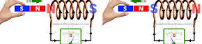
Consider a coil of wire and a galvanometer connected as shown with a magnet being moved towards the coil.
observations on experiments to verify Lenz’s law
When the north pole of the magnet is moved towards the coil, the galvanometer deflects to the left. This indicates that the direction of the induced current is clockwise. It follows the direction DCBA.
When the north pole of the magnet is moved away from the coil, the pointer deflects to the right. This indicates that current flow is in the anticlockwise direction or direction DABC.
Explanations on lenz’s law
As the north pole of the magnet approaches the coil, the induced current flows in the coil. It attempts to form an electromagnet with a north pole at the end near the incoming magnetic pole. This is meant to resist movement of the incoming north pole.
We study the magnetic effect of electric current. From this study, we can use the clock rule to determine the direction of the induced current. The current flow in the conductor is as illustrated below. The end near the north pole forms an opposing north pole.
Remember the basic law of magnetism states that:Like poles repel, unlike poles attract
Laboratory experiments on direction of induced current
click the image below to experiment about the direction of current:
The North pole of the magnet is moved away from the coil. The induced current flows in the coil. It forms a south pole at the coil’s end near the leaving magnet. This formation opposes the movement of the receding magnet. Using the clock rule, the direction of induced current flow is as illustrated in the diagram below.
From the above experiments and observations, the direction of the induced current in a coil can be determined in Lenz’s law which states that:
The direction of the induced e.m.f is such that the induced current which it causes to flow produces a magnetic effect that opposes the change producing it.
Lenz’s law applies the principle the principle of conservation of energy. Mechanical energy moves the magnet to the coil. This energy is converted to electrical energy. This conversion occurs in the form of an induced current. Hard work is needed to push the magnet towards the coil against a repulsive force that must be overcomed. This repulsive force comes from the induced pole of the coil which causes current to flow in an attempt to oppose the incoming pole.
Phase difference is the angular difference between two sinusoidal waveform of the same frequency. It tells us how much one wave is “ahead of” or “behind” another in terms of their cycles
The word phase in normal usage means any stage in a series of events or in a process of development.
Cambridge University dictionary defines phase as one of the stages or points in a repeating process measured from a specific starting point.
Two Waves can be of the same amplitude but with the different frequencies as shown in figure below.
The wave profile P makes it’s one complete oscillations before wave Q. Wave P has shorter wavelength compared to Q and hence P has higher frequency.
We can also see that P has smaller period as waves with shorter wavelength has smaller period.
Wave P completes it’s first cycle at A while Q finishes it’s first oscillation at B. We can say that P is leading Q. The maximum displacement of the two waves is the same hence they are operating at the same amplitude but different frequency. The two waves are said to be out of phase. Think about two radio receivers tuned to two different stations but with equal volume.
waves can also be of the same frequency but different amplitudes. Think of when we tune in our two radio receivers to the same station and then set them at different volumes
The figure below illustrates two waves operating at same frequency but at different amplitudes.
One wave is having more displacement than the other. However, they are arriving at the horizontal position simultaneously, as can be seen from the diagram. We say they are in phase.
Pendulum bobs in phase
To further illustrate the concept of phase and out of phase oscillations, consider two identical pendulums. The pendulums have bobs P and Q below.
We set the two masses, P and Q in oscillation. We give them some displacement on the left and then releasing them simultaneously. They have equal displacement because we have released at the same time. Therefore, they will pass through the lowest point Y simultaneously as they move in the opposite direction. They attain displacement together at Z and swing back together to complete the oscillation at x.
At any particular moment, the two masses will be moving in the same direction. They will also be at the same level of displacement in their oscillation. We say that the masses are oscillating in phase.
particles in phase difference
When particles in a wave motion happens to be oscillating in the same direction and at the same level of displacement,we say that their oscillation are in phase.
The diagram below have highlighted two positions of particles A and B. The particles are at the same displacement level from the reference line. They are both facing the same direction as indicated by the arrows. The particles A and B are said to be in phase and their distance apart is the wavelength λ of the wave motion whereas time taken to move from A to B is the periodic time T.
Particles in a wave motion can be in phase even if they have different amplitude.
In our previous pendulum oscillation of mass P and Q ; If P is Initially given a larger displacement than Q, the two will oscillate in phase. However, P will always be at a larger magnitude of displacement than Q.
A typical displacement time graph for two wave motions in phase with different amplitudes is shown below.
two waves in phase at different amplitude.
Oscillations out of phase
Consider two masses P and Q displaced from opposite directions from each other as in figure below.
When released simultaneously, they pass through the rest position at the same time. They move in opposite directions. They reach a point of maximum displacement at the same time. However, their maximum displacement is in opposite directions to each other.
Waves 180o out of phase difference
The two objects above are always at the opposite levels of displacement and their oscillations opposite direction to each other and they are said to be in opposite phase.
Wave motions that have same displacement and makes complete oscillations at the same time with their maximum displacements in exact opposite to each other are said to be in 180o phase difference (180o out of phase).
The figure below shows two wave motions at 180o phase difference.
Waves 90o out of phase difference
suppose in our pendulum oscillations we displaces the objects P and Q to X ; we release Q before P and then we release p when Q is exactly at Y. The angle of oscillation between P and Q will be 90o in difference and the resulting oscillation will be 90o out of phase.
The displacement time graph for waves 90o out of phase is illustrated below.
two waves can be out of phase at any angle. We are to see that in our future lessons.
The electromagnetic (EM) spectrum is the range of all types of Electromagnetic radiation. Radiation is energy that travels and spreads out as it goes – the visible light that comes from a lamp in your house and the radio waves that come from a radio station are two types of electromagnetic radiation.
Electromagnetic waves are transverse waves which results from oscillating electric and magnetic fields at right angles to each other.
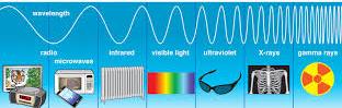
Electromagnetic spectra are arranged in order of their wavelength or frequency. This arrangement forms what is known as the electromagnetic spectrum.
A complete spectrum is shown below:
The figure below shows electromagnetic waves arranged in order of decreasing wavelengths
Properties of Electromagnetic waves
The Electromagnetic waves have the following common properties.
They travel through vacuum(space) with a speed of 3.0 x 10⁸ms-1 . This speed is usually referred to as the speed of light in vacuum and is usually denoted by c.
Do not require material medium for transmission
They are transverse in nature
Electromagnetic waves undergoes interference, reflection,refraction and polarisation effect
Posses energy in different amounts according to the relation E=hf where h is the Plank’s constant given as 6.63 x 10⁻³⁴ Js and f is the frequency
They carry no charge
They are not affected by electric or magnetic fields
Example: calculating energy of a wave
A certain electromagnetic radiation was found to be having a wavelength of 6.5 x 10⁻⁸ m. Calculate the energy it emits.
solution
To calculate the energy of a wave, you need to know its frequency. Then multiply the frequency by Planck’s constant.
Here we have only the wavelength, but we can get the frequency from the relation: v = fλ.
since it is an electromagnetic wave, it’s speed is 3.0 x 10⁻⁸ ms-1. and hence f=v/λ. that is:
=4.6154 x 10¹⁵ HZ
The energy of a wave was defined as E = hf where h (plank’s constant)= 6.63×10⁻³⁴ Js
hence E = 6.63 x 10-34 Js x 4.6154 x 1015 HZ≈ 3.06 x 10⁻²⁰J.
Wave is a form of energy. Wave energy is useful as well as dangerous to human beings. Communication technology uses concept of waves as its fundamentals. Earth quakes are as a result of seismic waves resulting from shifting of locks within the earth.
Phenomenon’s like formation of rainbows formation, mirages and thin films in oil shows presence of waves. Variations in quality of sound from musical instruments is based on the properties of waves.
Wave properties can be investigated by use of a ripple tank. Waves exhibits various properties that can be conveniently illustrated using a ripple tank.
The ripple tank
Ripple tank helps us study properties of water waves. Studying water waves can help us explain the characteristics of other types of waves such as light and sound waves.
Ripple tank consists of:
a transparent tray containing water
a point source of light above the tray
white paper screen and
an electric motor.
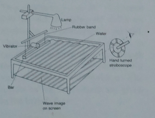
The white screen is underneath the tray while the electric motor is on the surface of the water in the tray. The figure below shows the basic structure of the ripple tank.
The water waves are the ripples traveling across the surface of the shallow water in the tray . This ripples are produced by the vibrations of the electric motor.
When you deep a finger in water, a pulse of wave is usually produced. This circular wave radiates outwards from the source of disturbance. This pulse in water is called a ripple. water ripples are progressive as they continuously propagate away from the source.
How ripple tank is used
A generator enables generation of continuous ripples. The electric motor is mounted on a wooden bar on a ripple tank. When the motor is started, the bar is made to vibrate by an electric metal disc on the axle of the motor.
To generate continuous straight waves, the length of the bar is adjusted so that it just touches the water surface. To generate continuous circular waves , a small ball called a dipper fitted to the bar is adjusted so that it just touches the water surface.see the figure below:
The figure below shows circular and line waves:
When the light from the lamp passes through the waves , the images of the waves are projected on the paper underneath.
Since the bottom of the tray is transparent, the light casts an image of the passing waves on the screen. When light from the lamp is passing through the water, the curve of the water surface acts like a series of lenses. These lenses are both converging and diverging that focus light to create a series of bright and dull lines. The wave crests produce bright lines while troughs produce dark lines. see the figure below.
To cut down unwanted reflections, the sides of the tray is aligned with spongy material.
For easier observations of the progressive waves, a stroboscope is used.
Stroboscope
A stroboscope is a disc with equally spaced slits which can be rotated by hand or a motor. If the speed of rotation is such that the wavefront advances one wavelength each time a slit passes through the eye, the wave fonts appears to be stationary. The waves are then said to be frozen.
Another type of stroboscope is made up of a lamp which flashes light on and off at a controllable measurable rate. At a frozen motion, the successive appearance of the slits at a particular point matches exactly with the period of the wave. this gives persistence of vision as the eye receives glimpses of the waves at the same level of displacement each time. The figure below illustrates observation of water waves through a stroboscope.
The wave pattern is represented by wavefronts lines that connects all the points that are in phase as the wave progresses. It follows that the distance between successive wave-fronts is equal to one wavelength.
Vocabulary of waves
oscillation
Also known as vibration. oscillation is when a wave makes one complete cycle of to and fro motion about the mean position.
the figure below illustrates a wave making one oscillation:
Amplitude
It is the maximum displacement of a particle from its rest position.
wavelength
This is the distance between two successive particles which are in phase and are moving to the same direction.
Frequency f
This is the number pf oscillations made by the wave in one second.
Contains information related to marketing campaigns of the user. These are shared with Google AdWords / Google Ads when the Google Ads and Google Analytics accounts are linked together.
90 days
__utma
ID used to identify users and sessions
2 years after last activity
__utmt
Used to monitor number of Google Analytics server requests
10 minutes
__utmb
Used to distinguish new sessions and visits. This cookie is set when the GA.js javascript library is loaded and there is no existing __utmb cookie. The cookie is updated every time data is sent to the Google Analytics server.
30 minutes after last activity
__utmc
Used only with old Urchin versions of Google Analytics and not with GA.js. Was used to distinguish between new sessions and visits at the end of a session.
End of session (browser)
__utmz
Contains information about the traffic source or campaign that directed user to the website. The cookie is set when the GA.js javascript is loaded and updated when data is sent to the Google Anaytics server
6 months after last activity
__utmv
Contains custom information set by the web developer via the _setCustomVar method in Google Analytics. This cookie is updated every time new data is sent to the Google Analytics server.
2 years after last activity
__utmx
Used to determine whether a user is included in an A / B or Multivariate test.
18 months
_ga
ID used to identify users
2 years
_gali
Used by Google Analytics to determine which links on a page are being clicked
30 seconds
_ga_
ID used to identify users
2 years
_gid
ID used to identify users for 24 hours after last activity
24 hours
_gat
Used to monitor number of Google Analytics server requests when using Google Tag Manager