Domestic wiring refers to the electrical wiring within a residential building. It encompasses the components and circuits that provide power for lighting, appliances, and other electrical needs. In domestic wiring, we studies: installation and connection of wires, switches, outlets, and other electrical devices. Understanding domestic wiring, ensures safe and reliable power supply.
what is domestic wiring
Domestic wiring refers to electrical connections that allows use of electric powers supplied by power providers .
Electrical power is usually supplied at 240V after the high voltage transmitted is scaled down through a local transformer. The high voltage transmission from power source could be 11000 V or more. The consumer will need only 240 V, therefore a step-down transformer will be needed.
Electric power is connected to a homestead from the transformer by use of two-wire cable. One cable is earthed at the transformer. The earthed wire is referred to as the neutral wire .
The earthed considered to be at zero electrical potential while the other wire is referred to as the live wire. The cable goes through the electrical company fuse box . The live wire is connected to a 60 A or high fuse value. The cable is then connected to the power meter where energy consumption is registered. From there it passes on to the consumer’s fuse box as illustrated.
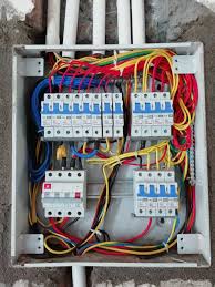
consumers fuse box in domestic wiring
It is the central part of an electrical system. It distributes electrical power and provides circuit protection. The figure below illustrates a common fuse box connections in a domestic wiring.

Here’s an overview of what it includes and what you should know:
The main switch
This is a double -pole switch which disconnects both the live and the neutral wire at the same time. disabling all the circuits in the house when needed. It is the main connecting link between external supply and household wiring . however, but we can have more than one mains switch.
The live busbar
This is a brass bar to which all live wires and the fuse are connected to. It connects to the live wire through the main switch. It connects the live wire of each circuit through a fuse.
Neutral busbar
This is the brass bar to which all neutral wires are connected to in domestic wiring.
Earth terminal
It is the earthed cable in the fuse box connected to the thick copper bar buried deep in the earth. It can also be earthed through water piping.
fuses
They are made of short thin wire mostly an alloy of cooper and tin. The alloy wire should have a low melting point. Fuses are used to safeguard against excess current in the circuit. When current exceeds the fuse rating, the wire gets very hot and melts hence disconnecting the circuit.
The melting disconnects the excess current which would have otherwise damaged the electrical appliances. Fuses also reduces risk of fire incase there is overheating in a circuit.


The circuit breaker
Circuit breakers are preferred over fuses protect electrical components from excessive flow for current.

When excess current flows through the circuit, increased magnetic power of the electromagnet opens the switch. This stops electric current flow. Once the problem causing the excessive current flow has been corrected , the switch is closed by mechanical means.
An advantage of circuit breakers over the fuses is that the circuit is broken simultaneously where the fuse melts slowly. The circuit breaker reset itself once the electric surge is corrected. This is unlike fuse that need to be replaced when it’s fuse wire melts.
common symptoms of electrical problems in domestic wiring
- repeatedly Tripping circuits
- Burning smell or scorch marks
- Buzzing sounds
Distribution of power from the consumers unit
House wiring systems distribute electricity throughout a building. Common systems include cleat, casing & capping, batten, lead sheathed, and conduit wiring. conduit is considered the most popular and safest, involving pipes (metal or PVC) to house wires.
consider the setup below:

Each component is has a wire running from the live busbar through an appropriate fuse or circuit breaker. There is also a return wire running from the neutral busbar to the output terminal.
Except for the lighting circuit, other circuits have an earth connections running from the earth terminal to the socket. Appliances that requires earthing are automatically earthed through the socket making them safe to handle. Not earthing some appliances exposes danger to the consumer because they can be shocked while using them.
The lighting circuit
In lighting circuit, lamps are connected in parallel so that they operate at the same mains voltage and also operate independently. Switches are placed on live wire for safety purposes.
If the switch was on neutral wire, the wire would still be connected to the mains potential even when the switch is off. This would cause an electric shock when one handles any conductor linked to the live wire.
since lighting circuit carries relatively low current, the wire used is relatively thinner than those of other circuits. In an ordinary house, power for the lighting is usually supplied through 5A fuse .This is because each lamp takes only a small current.
The two ways switch circuit
A two-way switch circuit allows a lamp or other electrical device to be controlled from two different locations. This is achieved by using two or more switches that are connected in a specific way.
In this circuit, an electric lamp can be operated by any one of the two switches. The circuit allows a bulb to be put on by one switch and be put off by the other switch. The most common application is for controlling staircase lights from both the top and bottom of the stairs. A switch at the bottom of the staircase can be used to put on the light. The switch on the top of the staircase then turns it off. A lamp can be turned on by a switch at the door. Another switch at the other end of the room turns it off.
Figure below illustrates a two way switch:

when the contact is made at poles A and B as illustrated on the diagram, the bulb lights. The same thing happens when contact is made at C and D simultaneously.
To put off the bulbs at point P, the switch is made to make contact at C while Q is in contact with B. To put on the bulb again at Q, the switch is made to contact D. At that point, P and C are in contact with each other.
The ring mains circuit
A ring main circuit, also known as a ring circuit. is a type of electrical circuit used in many UK homes to distribute electricity to power sockets. It’s characterized by a looped cable that runs from the consumer unit (fuse box), through multiple sockets, and back to the consumer unit. This looped design allows electricity to reach a socket from either direction, reducing the load on the cable compared to a single-direction radial circuit
The figure below illustrates the ring mains circuit.

The power for the sockets in the various rooms is tapped at convenient points from the loop. The lop arrangement of the cable enables a double path for the current. The loop arrangement also effectively increases the thickness of the wire used. This reduces the risk of overloading the circuit when several sockets are in use.
Appliances using the ring main circuit are provided with a third wire connected to the casing. From the power socket, the third wire links with the earth terminal at the consumer unit through the mains circuit earth wire. If the live wire accidentally touches the casing, it makes it live. A large current flow through the earth wire. The large current will causes the fuse to blow, cutting off the current. Anyone handling the appliance will thus be safe from possible shock.
The cooker circuit
A cooker circuit refers to the electrical circuit dedicated to powering an electric cooker. Typically a hob and oven, in a domestic setting. It’s designed to handle the high power demands of cooking appliances. It usually involves a dedicated circuit breaker, a cooker control unit (CCU) and specific wiring configurations.

The cooker circuit has the same connection and design with water heater circuit. They are both supplied with own electric circuits. These are earthed and their wires are relatively thicker than those for the lighting circuits as they carries large currents.
The three pin plug
A three-pin plug is a type of electrical plug used to connect an appliance to the power supply. It has three metal pins (or prongs) that fit into matching holes in a socket. A three pin plug connects appliances to power source through a socket.

A three-pin plug has three terminals labeled L, N and E. They represent live, neutral and earth pins respectively. The three leads from the appliances are connected to the three pins as shown:

The insulation on the three leads on the power circuit are colored differently. This enables us link correctly when connecting to the power circuit. The live wire is colored red or brown. The neutral wire is colored blue or black while the earth is colored green or green with yellow stripes.
The three pin plug circuit is represented as shown on diagrams:


A fuse is used in the plug to safeguard the appliance from the damage due to excessive current in the circuit. The rating of the fuse depends on the operating current of the appliance. The value of the chosen fuse should always be slightly above the value of the operating current of the appliance. An appliance operating at 4 A will need about 5A fuse as the most appropriate fuse. An 13 A fuse would be suitable for an appliance of around 11 A.
Related topics
- Induced Electromotive Force(E.M.F)
- The Electric Motor
- An a.c Generator
- Transformers
- current and electricity
- Examination questions on current electricity
- Electromagnetic waves
- Field patterns for a straight Current carrying conductor