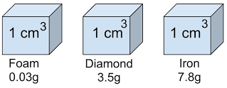
Exam questions on density often involve several concepts. This includes; calculating density, comparing densities of different substances, or understanding how density relates to buoyancy and floating. Density is a measure of how much mass is packed into a given volume. It’s calculated by dividing an object’s mass by its volume.
Exam Questions on density
1.(a) The level of water in a measuring cylinder rises from the 50 cm3 mark to 55.7 cm3 marks when a metal block weighing 45 g is submerged in the water in the cylinder.
(i) Calculate the density of the metal block
(ii) State two differences between density and relative density.
2. (b) In an experiment to determine the density of solid S which is not soluble in water. A student obtained the following;
-Mass of empty density bottle= 20 g
-The Mass of density bottle when full of water =45 g
-Mass of density bottle with small quantity of solid S =152 g
-Mass of density bottle with small amount of solids S topped up with water =167 g.
Given that the density of water is 1 g/cm3.Find; i. The volume of the density bottle
ii. The mass of the solid S iii. The volume of the solid S
2. The volume of a solution was measured as below. If the mass of solution is measured to be 60.75 grams, what is the density of the solution? (2 marks)
solution level as seen on a measuring cylinder
3. What is the mass of a cylinder of lead that is 2.50 cm in diameter, and 5.50 cm long. The density of lead is 11.4 g/cm3.
(i) Calculate the volume in two decimal places of the cylinder. Take π=3.14 (3 marks)
(ii) Determine the mass of the cylinder. Leave your answer as a whole number. (3 marks)
4. Exam questions on density
4. The mass of an empty density bottle is 20 g. Its mass when filled with water is 40.0 g and 50.0 g when filled with liquid A.
(i) Determine the mass of water in kilograms. (3 marks)
(ii)Find the mass of liquid A (in kilograms). (3 marks)
(iii) Find the volume of water. (2 marks)
Calculate the density of liquid A if the density of water is 1,000 kgm-3. (2 marks)
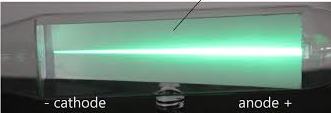
Cathode rays are streams of negatively charged particles, or electrons, which are accelerated from a cathode to the anode within a vacuum tube by an electrical potential.
These rays travel to the positively charged anode, creating a visible beam. They are also known as electron beams and were instrumental in the discovery of the electron.
Before the electrons are accelerated, they must be extracted from a atoms and be on the surface. Electrons are first extracted from from the nuclei to a metal surface when the metal is heated. The heat energy raises the energy of an electron. This enables it to break loose from the force of attraction of the nuclei. This process where electrons are emitted to the surface is known as thermionic emission.
When a material is heated, its atoms vibrate more vigorously. This thermal energy can be transferred to the electrons in the material. If the temperature is high enough, some electrons gain enough energy to overcome the work function of the material. Work function is the minimum energy needed for an electron to escape from the surface of the material. It escapes into the vacuum or surrounding environment.
Thermionic Emission for cathode rays
In thermionic emission, a cathode is heated from low voltage supply so that electrons can be extracted to the surface. Another higher voltage is then used to accelerates the electrons produced towards an anode. A typical setup used for thermionic is as shown below.
A cathode which is inside the evacuated glass tube is made with mixture of barium oxides and strontium oxide. The resulting metal oxide has a low work function. This means that the minimum energy required to remove an electron from its atom to the surface is low.
In the setup a low voltage of about 6V drives a current through the heating filament which then heats the cathode
Initially the reading on the milliammeter(mA) is zero. When the heater circuit is switched on, some current is observed on the milliammeter after some time. This means that the current circuit between the cathode and the anode has been completed. There is a wide gap between the anode and the cathode. However, when the heater current is switched on, the heater circuit is complete in the gap.
This is because cathode the electrons produced by the cathode are able to move to the anode across the gap. How do they do that?
The hot cathode emits electrons which are then attracted to to the anode due to the 12V accelerating potential. This acceleration ensures electrons are able to move across the gap hence making the circuit complete. This setup allows us to observe thermionic emission. It helps explain the cathode rays inside the evacuated glass tube we call a cathode ray tube.
Production of cathode rays
Cathode rays are usually produced in cathode ray tube (CRT).
A cathode ray tube
Electrons produced at the cathode by thermionic emission are accelerated towards a fluorescent screen. This fluorescent screen connected to the anode which is connected to the positive terminal of an extra high tension (E.H.T) source. When cathode rays are stopped by the fluorescent screen, the kinetic energy of the cathode causes the screen to glow.
The reason the tube is evacuated is to ensure electrons do not collide with gaseous particles before reaching the screen. If electrons collides with other particles, ionization of the gas in the tube occurs. This is found to be causing different observations from the one intended. Collision with some other particles can cause electrons to loose their energy and probably not able to reach the screen. The movement of cathode rays in a cathode ray tube is illustrated in the table figure below:
Questions
What is thermionic emission
Illustrate production of cathode rays using a suitable diagram.
Explain why it is important for a cathode ray tube to be evacuated.
Domestic wiring refers to the electrical wiring within a residential building. It encompasses the components and circuits that provide power for lighting, appliances, and other electrical needs. In domestic wiring, we studies: installation and connection of wires, switches, outlets, and other electrical devices. Understanding domestic wiring, ensures safe and reliable power supply.
what is domestic wiring
Domestic wiring refers to electrical connections that allows use of electric powers supplied by power providers .
Electrical power is usually supplied at 240V after the high voltage transmitted is scaled down through a local transformer. The high voltage transmission from power source could be 11000 V or more. The consumer will need only 240 V, therefore a step-down transformer will be needed.
Electric power is connected to a homestead from the transformer by use of two-wire cable. One cable is earthed at the transformer. The earthed wire is referred to as the neutral wire .
The earthed considered to be at zero electrical potential while the other wire is referred to as the live wire. The cable goes through the electrical company fuse box . The live wire is connected to a 60 A or high fuse value. The cable is then connected to the power meter where energy consumption is registered. From there it passes on to the consumer’s fuse box as illustrated.
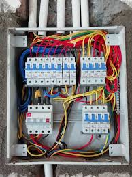
consumers fuse box in domestic wiring
It is the central part of an electrical system. It distributes electrical power and provides circuit protection. The figure below illustrates a common fuse box connections in a domestic wiring.
Consumers fuse box
Here’s an overview of what it includes and what you should know:
The main switch
This is a double -pole switch which disconnects both the live and the neutral wire at the same time. disabling all the circuits in the house when needed. It is the main connecting link between external supply and household wiring . however, but we can have more than one mains switch.
The live busbar
This is a brass bar to which all live wires and the fuse are connected to. It connects to the live wire through the main switch. It connects the live wire of each circuit through a fuse.
Neutral busbar
This is the brass bar to which all neutral wires are connected to in domestic wiring.
Earth terminal
It is the earthed cable in the fuse box connected to the thick copper bar buried deep in the earth. It can also be earthed through water piping.
fuses
They are made of short thin wire mostly an alloy of cooper and tin. The alloy wire should have a low melting point. Fuses are used to safeguard against excess current in the circuit. When current exceeds the fuse rating, the wire gets very hot and melts hence disconnecting the circuit.
The melting disconnects the excess current which would have otherwise damaged the electrical appliances. Fuses also reduces risk of fire incase there is overheating in a circuit.
An electric fuse
fuse symbol (old)
fuse standard symbols
The circuit breaker
Circuit breakers are preferred over fuses protect electrical components from excessive flow for current.
When excess current flows through the circuit, increased magnetic power of the electromagnet opens the switch. This stops electric current flow. Once the problem causing the excessive current flow has been corrected , the switch is closed by mechanical means.
An advantage of circuit breakers over the fuses is that the circuit is broken simultaneously where the fuse melts slowly. The circuit breaker reset itself once the electric surge is corrected. This is unlike fuse that need to be replaced when it’s fuse wire melts.
common symptoms of electrical problems in domestic wiring
repeatedly Tripping circuits
Burning smell or scorch marks
Buzzing sounds
Distribution of power from the consumers unit
House wiring systems distribute electricity throughout a building. Common systems include cleat, casing & capping, batten, lead sheathed, and conduit wiring. conduit is considered the most popular and safest, involving pipes (metal or PVC) to house wires.
consider the setup below:
Each component is has a wire running from the live busbar through an appropriate fuse or circuit breaker. There is also a return wire running from the neutral busbar to the output terminal.
Except for the lighting circuit, other circuits have an earth connections running from the earth terminal to the socket. Appliances that requires earthing are automatically earthed through the socket making them safe to handle. Not earthing some appliances exposes danger to the consumer because they can be shocked while using them.
The lighting circuit
In lighting circuit, lamps are connected in parallel so that they operate at the same mains voltage and also operate independently. Switches are placed on live wire for safety purposes.
If the switch was on neutral wire, the wire would still be connected to the mains potential even when the switch is off. This would cause an electric shock when one handles any conductor linked to the live wire.
since lighting circuit carries relatively low current, the wire used is relatively thinner than those of other circuits. In an ordinary house, power for the lighting is usually supplied through 5A fuse .This is because each lamp takes only a small current.
The two ways switch circuit
A two-way switch circuit allows a lamp or other electrical device to be controlled from two different locations. This is achieved by using two or more switches that are connected in a specific way.
In this circuit, an electric lamp can be operated by any one of the two switches. The circuit allows a bulb to be put on by one switch and be put off by the other switch. The most common application is for controlling staircase lights from both the top and bottom of the stairs. A switch at the bottom of the staircase can be used to put on the light. The switch on the top of the staircase then turns it off. A lamp can be turned on by a switch at the door. Another switch at the other end of the room turns it off.
Figure below illustrates a two way switch:
when the contact is made at poles A and B as illustrated on the diagram, the bulb lights. The same thing happens when contact is made at C and D simultaneously.
To put off the bulbs at point P, the switch is made to make contact at C while Q is in contact with B. To put on the bulb again at Q, the switch is made to contact D. At that point, P and C are in contact with each other.
The ring mains circuit
A ring main circuit, also known as a ring circuit. is a type of electrical circuit used in many UK homes to distribute electricity to power sockets. It’s characterized by a looped cable that runs from the consumer unit (fuse box), through multiple sockets, and back to the consumer unit. This looped design allows electricity to reach a socket from either direction, reducing the load on the cable compared to a single-direction radial circuit
The figure below illustrates the ring mains circuit.
The power for the sockets in the various rooms is tapped at convenient points from the loop. The lop arrangement of the cable enables a double path for the current. The loop arrangement also effectively increases the thickness of the wire used. This reduces the risk of overloading the circuit when several sockets are in use.
Appliances using the ring main circuit are provided with a third wire connected to the casing. From the power socket, the third wire links with the earth terminal at the consumer unit through the mains circuit earth wire. If the live wire accidentally touches the casing, it makes it live. A large current flow through the earth wire. The large current will causes the fuse to blow, cutting off the current. Anyone handling the appliance will thus be safe from possible shock.
The cooker circuit
A cooker circuit refers to the electrical circuit dedicated to powering an electric cooker. Typically a hob and oven, in a domestic setting. It’s designed to handle the high power demands of cooking appliances. It usually involves a dedicated circuit breaker, a cooker control unit (CCU) and specific wiring configurations.
The cooker circuit has the same connection and design with water heater circuit. They are both supplied with own electric circuits. These are earthed and their wires are relatively thicker than those for the lighting circuits as they carries large currents.
The three pin plug
A three-pin plug is a type of electrical plug used to connect an appliance to the power supply. It has three metal pins (or prongs) that fit into matching holes in a socket. A three pin plug connects appliances to power source through a socket.
A three-pin plug has three terminals labeled L, N and E. They represent live, neutral and earth pins respectively. The three leads from the appliances are connected to the three pins as shown:
The insulation on the three leads on the power circuit are colored differently. This enables us link correctly when connecting to the power circuit. The live wire is colored red or brown. The neutral wire is colored blue or black while the earth is colored green or green with yellow stripes.
The three pin plug circuit is represented as shown on diagrams:
Three-pin plug
The socket for three-pin plug
A fuse is used in the plug to safeguard the appliance from the damage due to excessive current in the circuit. The rating of the fuse depends on the operating current of the appliance. The value of the chosen fuse should always be slightly above the value of the operating current of the appliance. An appliance operating at 4 A will need about 5A fuse as the most appropriate fuse. An 13 A fuse would be suitable for an appliance of around 11 A.
Rectilinear Propagation of waves means straight line travel of waves. It is a property that describes wave as traveling in a straight lines and perpendicular to the wavefront.
To illustrate rectilinear propagation of waves, consider the ripple tank that is set to produce plane waves.
Two rulers are placed underneath the tray of the ripple tank. They are parallel to each other and perpendicular to the bar so that the waves produced are plane waves.
Consider the setup below;
Illustrating rectlinear Propagation of waves in a ripple tank
When we start the vibrator and adjust it to the appropriate frequency, the wave fronts are perpendicular to the wavefront.
If we replace the straight bar attached to the vibrator with a small ball, the vibrator produces circular waves that propagates as illustrated below.
We can then adjust the rulers beneath the tray such that they are perpendicular to the wavefronts. We see that the circular waves moves outwards from the source and always perpendicular to the wavefronts.
From here we see that waves are propagated along straight lines.
Wavefronts
A wavefront is an imaginary line which joins a set of particles which are in phase for a wave in wave motion . While observing wave motion in a ripple tank, wavefronts can be seen on the white paper. The formation of circular wavefronts and plane wavefronts are as shown.
Circular and plane wavefronts
A ray in wave propagation
A ray is an idealized line that represents the direction of energy flow or wave propagation in a medium.
In waves, a ray is a line drawn perpendicular to the wavefront showing the direction of travel of the wave energy. See the figure below
The figure shows that the direction of wave travel is perpendicular to the direction of vibration.
The High voltage transmission is used to carry electricity over long distances with minimized power loss. When electricity is transmitted at high voltages (e.g 110 kV, 220 kV, or even 765 kV). less energy is lost as heat due to resistance in the wires. In the high voltage transmission, Power stations usually generate an alternating current a.c at a voltage between 11KV and 25KV. The power generated is then stepped up to 132KV-400KV so that it can be transmitted to long distances from the power station. The electrical power is usually transmitted over long distance to substations where the voltage is stepped down to 11KV. From the substations, power is distributed to consumers . This is after being stepped down to the consumable levels according to the needs of each consumer. Consumers can be heavy industry that may need over 30KV. light industry that may need over 10KV or domestic homes that may need only 240V.
Dangers of High Voltage Transmission
risk of electric shock incase poles collapse or cables hangs too low
The cables can cause fire on nearby structure and vegetation when cables are too loose
Because of the high voltage, there is strong electric fields that can interfere with health of people exposed to such fields.
During thunder and lightening, the cables can conduct excess charges from the lighting causing danger to houses and machines using electricity.
during strong wind, the cables can come into contact with each other causing fire.
Power losses During High Voltage Transmission
Given that; I=current flowing, V=voltage supplied and R =electrical resistance in the High voltage transmission cables :
Power dissipated in a circuit is given by ; P=VI
From ohm’s law V = IR. Hence, P = (IR)I = I2R
This means that for a given resistance in a circuit, when the current is high , the power loss is large and when the current is low, the power loss is small.
Power loss in High voltage transmission is therefore low when it is transmitted at high voltage and low current.
To attain high voltage and low current, output voltage from power station is stepped up for long distance transmission. This is done to minimize power losses in transmission cables. We do this is ensuring the current is as low as possible with the same power output.
Since long distances are involved, the transmission cables are thick and made from very good conductors of electric current to ensure resistance is kept to minimum.
aluminum cables are preferred in high voltage transmission because :
It is a good conductor of electric current
It can be obtained cheaply
It is light
Example problem
The resistance a of power transmitting cable is 10Ω and is used to transmit 11Kv at 1A current. If this voltage is stepped-up to 16kv by a transformer, determine the power loss.
solution
assuming the transmission is 100% efficient:
power input = power output
VpIp = VsIs
11000 x 1 = 160 000 x Is
= 0.069A
power lost = I2R = (0.069)2 x 10 = 0.048W
If there was no stepping up of the voltage the power loss would be:
power loss = (1.0)2 x 10 = 10W which is actually 200 times wastage compared to power calculated above.
Practice Question on the high voltage transmission
A generator produces 750kW at a voltage of 15kV. For high voltage transmission, This voltage is stepped up to 125kV .It is to be transmitted through cables of resistance 0f 500 Ω to a step-down transformer in a substation. Assuming that both transformers are 100% efficient:
(a) calculate:
(I)The current produced by the generator
(ii) the current that flows through the transmission cables
(iii) the voltage drop across the transmission cables
(iii) power lost during transmission
(iv) power that reaches substation
solution
(I)
power input = Voltage in primary coil x Current in the primary coil
that is: power input = Vp x Ip
Current in primary Ip will therefore be given us:
Ip=PVp
and substituting for the values of power and primary voltage we have:
Ip=750∗1000w15000V=50A
so the current produced originally in the primary coil is 50.0A
(ii)
At the step-up transformer;
power input = power output (no power is lost because the transformer is 100% efficient)
that is: power in primary generator = power after step up
Vp x Ip = Vs x Is
15000V x 50A = 125000xIs
Is=15000V∗50A125∗1000=6A
Power losses during high Voltage transmission
Power losses is common during high voltage transmission . High voltage power transmission involves moving electrical power from the source where it is being generated to consumer premises (sometimes hundreds of kilometers way) where it need to be used.
In high voltage power transmission, power loss during transmission is minimized by transporting electrical power in high voltage but at a small current. High voltage transmission involves transporting electrical power over long distances through electrical cables. From electricity topics, we learn that conductors have some resistance to the flow of currents. The resistance in a conductor is proportional to the length of the conductor. Power losses during transmission is caused by the heating effect that results from resistance of current in the conductor. Because the distance involved can be hundreds of kilometers, power losses can be significant.
Power losses during transmission
we determines power dissipated in a circuit from the relation:
Power P = VI.
Where V is voltage across the circuit and I is the current flowing in the circuit.
From Ohms law of electric current; V= IR. Where R is the resistance in the circuit.
Therefore, Power = (IR)I = I2R.
From the equations above, you can see that power loss can be high when current is high for a given resistance value in the conductor.
Because power is constant, the idea of transmitting power efficiently is by increasing its voltage. Increasing voltage ensures reduced current for the same power source. The best way to minimize power loss during transmission is to transmit at very high voltage. It should also be done at the smallest current possible. We usually step up the voltage produced at the source to high voltage values. This adjustment brings the current closer to zero as much as possible.
power providers can also reduce electrical resistance in transmission cables by choosing cable with thick diameter but one that is a good conductor of electricity.
Power providers prefers aluminum as thee best choice for transmission cables since it is a good conductor, cheap to obtain and it is not heavy. An alternating current power source is the one preferred in high voltage transmission because it is can easily stepped up and down when needed.
Example Problems
A power company uses a power cable of with overall resistance of 5000Ω to transmit 10Kv at a current of 0.8A. They use a transformer to step up this voltage to 25KV by a transformer, determine:
(i) power loss expected if there was no step-up
(ii) power loss expectations after step-up
(iii) percentage ratio between power power lost before step-up to power loss after step-up
solution
(i) Power = I2R.
hence power loss when voltage is not stepped up=(0.8)R x 5000=3200 watts.
(ii) Assuming that there is no power loss in the transformer; After stepping up the following equation applies:
power before step-up = power after step-up.
power before step-up is the power fed into primary coil of the transformer;
Using the transformer equation; Power in primary coil = power in the secondary coil.
That is; VpIp = VsIs
substituting in the equation to get the current after stepping up we have:
10000v x 0.8A = 25000v x Is
and hence;
Is=10000V∗0.8A25000= 0.32A
stepping up has reduced current flow from 0.8A to 0.32A
power lost due to this new current will be:
Power lost = (0.32)2 * 5000 = 512 watts
(iii) The ratio of power lost before stepping up to power lost after stepping up will be
powerratio=3200watts512watts∗100= 625%
from the above working, one can see that power loss has been reduced by 625% when power is stepped up from 10KV to 25KV. This proves to us that stepping up power to reduce current contributes to reduction of power loss in a big way.
Question for practice
A generator produces 700kW at a voltage of 15kV. The voltage is stepped up to 125KV and the power transmitted through the cables of resistance 300Ω to a step-down transformer in a sub-station. Assuming that both transformers are 100% efficient:
(a) calculate:
(i) The current produced by the generator
(ii) The current that flows through the transmission cables
Electric circuits are pathways through which electric current flows. We can make simple electric circuits using simple apparatus and procedure. An electric current is the flow of electric charge through a conductor, such as a wire. It occurs when charged particles move. Typically, electrons respond to an electric field created by a voltage difference across the conductor. Voltage difference is provided by a cell or a battery.
A cell is a device that converts chemical energy into electrical energy, providing a source of electrical power. It consists of one or more electrochemical reactions that generate a flow of electrons, which is the electric current. A battery is a combination of two or more cells.
The figure below shows a dry cell that is common in making of many simple circuits.
a dry cell
The figure below three dry cells connected to make a battery:
battery of cells
Cell provides the energy required to pump electrons in a conductor so that they can move in a closed loop. A cell creates voltage difference by creating a region of excess electrons on one side and deficit of electrons on the other side through chemical reactions. A conductor is connected such that it runs from one side of the cell to the other in a closed loop.
When there is no gap between the two ends of the cell or battery along the conductor, the circuit is said to be complete. Charge flows only when the circuit is complete. Cell acts as the pump to push the charges along the conductor so that they can be on the move.
The end of battery with excess of negative charge is called the negative terminal. The other end with with deficit of charge is known as the positive charge. Charge flows from negative terminal of a cell towards the positive terminal. Current flows in opposite direction conventionally form positive terminal of the battery towards the negative end. Current is when charges flow and is a function of the speed of flow of charges. Infact the formal definition of current is that current is the rate of flow of charges. The standard international unit of current is called Ampere (A).
From the definition of current:
Current(I)=charge flowing through a section of conductor per unit time(t)
I=Qt where I is the current and Q is the amount of charge flowing
charge is measured in coulombs while time is in seconds. Therefore Ampere is the number of coulombs per second.
Example:
What is the current flowing through a bulb where 100 coulombs of charge is observed to flow for 1.8 minutes?
solution
I=Qt
=10060×1.8=100108=0.926 A
Example 2:
what amount of charge is flowing through a conductor where current flowing is 6.0 A
solution
I=Qt=Q x 1 second
6.0=Q x 1 second
Q = 6.0 coulombs
Making of Simple Electric Circuits
A simple electric circuit consists of a few basic components arranged in a loop that allows electric current to flow. The most basic components of a simple circuit includes:
Power Source
This is typically a battery or a cell that provides the electrical energy to push the charge around the circuit. The positive and negative terminals of the power source create a voltage difference that drives the current.
Conductor
These connect the components of the circuit and provide a path for the current to flow. The most common material to make conductors is copper wires. Other useful material to make electric current is aluminum wire. other wise most of metallic materials can conduct electric current.
Load
A load is any component that uses electrical energy. It performs a function, such as a light bulb, motor, or resistor. The current passes through the load, and energy is transferred to it (e.g., light or heat).
Switch
A switch is used to control the flow of current in the circuit. When the switch is open, the circuit is incomplete, and current does not flow. When the switch is closed, the circuit is complete, and current flows.
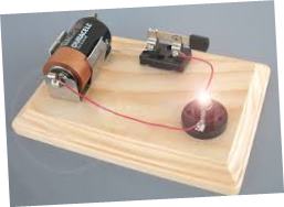
The simplest of electric circuit is made up battery and a conductor.
A very simple circuit made of a dry cell and a conductor
This circuit above is simple and naive , to make a working circuit, you need to some few extra components.
The bulb is used to show that current is flowing when the bulb lights. Opening the switch makes the bulb off showing that current off have been cut off. Current is conventionally set to flow opposite direction to the flow of charge.
Convectional Circuit Diagram
For clarity and neatness, symbols are used in representing components of an electric circuit. It would be tedious and clumsy to draw each of the components used in circuits. Therefore, we use symbols so that we can easily represent circuits in diagrams.
The figure below shows the circuit that was shown above drawn in convectional ways using symbols.
An open circuit
On the diagram above, there is a gap on the switch. The loop from the positive terminal of the cell towards the negative one has a gap. The circuit is said to be incomplete or open. No current is flowing in such circuit and is usually referred as an open circuit.
Switch acts like a gate, it connects two parts to make the circuit complete. When switch is closed, the circuit becomes complete. The figure below shows a complete circuit.
A closed circuit
In the diagram below, current will flow from positive of the battery to the negative without encountering a gap. the bulb with thus light because it is in a closed circuit.
While drawing or interpreting circuit diagrams, Connecting wires are drawn as straight lines with right angle corners. However, the actual wires are flexible and bent.
The arrow-heads drawn on the lines indicates direction of the flow of current. Remember that, current flows opposite direction to that of charge flow.
Short circuiting
Short circuiting is a condition where an electric current is caused to flow through a path of low resistance to avoid the path with high resistance.
Electric current usually follows a path of least resistance when moving.
consider the figure below.
short circuiting a cell and a bulb
Bulb is considered to be of much higher resistance compared to the conducting wire. In the above connection, current will flow through wire AB and avoid passing through the bulb. The bulb with thus not light and is said to be short circuited. In the figure above, both the cell and the bulb are short circuited.
In the figure below only the bulb is short circuited.
short circuiting a bulb
Common electrical symbols used in circuit diagrams
each component in a circuit diagram has a unique symbol that represent it. The table below summarizes information about most of components used in circuit diagrams and their symbols.
Electromagnetic induction, the phenomenon where a changing magnetic field induces a voltage in a nearby conductor, has numerous practical applications. Some applications of electromagnetic induction include electric generators, transformers, induction cooking, and magnetic flow meters.
applications of electromagnetic induction: induction coil
Induction coil is an important application of the electromagnetic induction. The induction coil consists of few turns of thick insulated copper wire wound on a primary coil. Then a secondary coil of many turns of thin insulated copper wire. we wound Both primary and secondary coil on a soft iron core. see the figure below:
The structure and working of the induction coil
we connect the primary coil to a direct current source of low voltage. In the figure below , we have wound the primary and secondary coil on top of the other.
When we close the switch , the soft iron core becomes magnetised due to the current in the primary coil. This causes it to attract the soft iron armature. The moving armature armature opens the contacts and cuts off the primary current, rapidly reducing the magnetic field to zero. This induces a large a large e.m.f in the secondary coil by mutual induction. However, the spring pulls the armature back to its initial position. This action completes the circuit again in the primary circuit so that the current flow again. This process repeats itself.
The switching on and off of the primary coil is thus continuous hence continuous changing magnetic flux. The induced e.m.f in the secondary coil is much higher when the primary coil is switching off than when switching it on. Remember the rate of current decay is usually higher than the rate of current build up in electromagnetic induction.
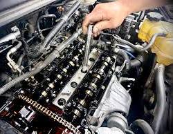
Many secondary coil increases the magnitude of the induced e.m.f in the secondary coil.Spark then jumps across the gap G between the two ends of the secondary coil. Hence can be used to ignite petrol-air mixture in a car engine.
Sparks may also occur at the contacts due to magnetic field of the primary coil. This cuts the primary coil fulfilling the Lenz’s law to keep primary current flowing.
A capacitor connected across the contacts minimizes the sparking. This causes the primary current and hence the magnetic flux to decay smoothly to zero.
some applications of electromagnetic induction: The moving-coil Microphone
The moving-coil microphone is a popular application of the electromagnetic induction. A coil of wire is wound on a cylindrical former connected to a diaphragm and placed between the poles of a magnet. see the diagram below:
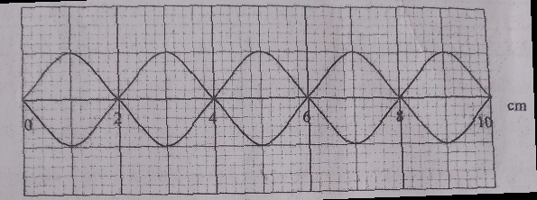
Sound waves from a source sets the diaphragm in vibration. Figure below shows a typical wave profile :
This way, it causes the coil to move to and fro, cutting the magnetic field. The field is radial so that the motion is perpendicular to it for maximum flux linkage. An induced e.m.f of varying magnitude sets up varying current in the coil. An amplifier is used to increase the amplitude of this current before it is fed into a loudspeaker. In the loudspeaker, it is converted back to sound.
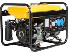
An Alternating current (a.c) Generator is also refereed to as the alternator. An a.c generator is a device or machine that converts mechanical energy energy into electrical energy. It does this by rotating conductors through magnetic fields.
The figure below illustrates a simple generator. It is made of curved permanent rectangular magnetic poles, slip rings, a conductor made into a loop, and carbon brushes.
The poles of magnets are curved so that the magnetic field is radial. Current enters and leaves the coil through the brushes which are pressing against the slip rings.
Carbon brushes are preferred because they are good conductor, slippery to allow the wire slide along with ease and acts as a lubricant. The figure illustrates a.c generator more vividly.
working of an a.c Generator
The ac generator will produce electric current in the coil when the coil rotates through magnetic field using the principle of electromagnetic induction.
When the coil rotates clockwise as indicated on the diagram at the rotation axis, edge AB rotates upwards. Meanwhile, edge CD rotates downwards. This causes the two edges to cut the magnetic field at right angles while in the horizontal position. The induced e.m.f is maximum when the coil is perpendicular to the magnetic field.
Determining direction of current in a.c generator
Using the Fleming’s right-hand rule, the flow of current is in direction A-B-C-D when the direction of rotation is clockwise. The induced current flows through the external circuit via the slip rings and through carbon brushes.
As the coil rotates from a horizontal to a vertical position, the angle at which the sides of the coil cut the magnetic field decreases. It changes from 90o to 0o. This causes the induced e.m.f to reduce from its maximum value (Eo) to zero e.m.f. when the coil becomes positioned vertically
An overview of the cross-section of the coil in a magnetic field is shown below.
The coil rotates past the vertical position. At that moment, the sides AB and CD move parallel to the field. In that position, the coil does not cut the magnetic field. Therefore, the induced e.m.f is zero at that position.
Past the vertical position, side AB and CD exchange position. Side AB starts moving downward while CD moves upward. The angle increases from 0o to 90o. This occurs as the sides of the coil cut the magnetic field and the coil returns to the horizontal position.
When the angle is increasing from zero to 90o , the induced e.m.f increases from zero to maximum value Eo. When AB and CD exchange positions in the coil rotation, the direction of current flow reverses to D-C-B-A. This action makes brush y positive and makes brush x to be negative.
As the coil rotates further to complete one revolution, its sides cut the magnetic field at a changing angle. This angle reduces from 90o to 0o. Consequently, the e.m.f induced in the coil reduces from maximum value Eo to zero.
induction of e.m.f in the a.c generator
The variation of the e.m.f increases from zero to maximum at one quarter cycle. Then it reduces from maximum to zero at the next quarter circle. Next, it starts increasing to maximum value in the negative direction in the third cycle. At the fourth cycle, it increases from maximum negative value to zero. Thus, in one complete oscillation of the coil, the variation of induced e.m.f against the angle of rotation forms a sinusoidal curve. The curve formed by this variation can be represented by the equation:
E = Eo sin θ
where E is an instantaneous e.m.f at any particular angle of rotation where Eo is the maximum e.m.f and θ the angle between plane of the coil and the vertical axis.
The formation of the sine curve is as illustrated
By ohms law;
$$I=\frac{E}{R}$$
where R is the resistance of the circuit and I is an instantaneous current at random position of ration of the coil.
$$Therefore, I = \frac{E_o}{R}sin\theta$$
A typical graph of e.m.f against the angle θ is as illustrated
After one complete circle, the rotation pattern repeats itself and many circles are made per unit time. The number of cycles made per second is referred as the frequency of the generator and is also the frequency of the a.c current.
Most of generators used to make commercial power productions makes 50-60 revolutions per second. In USA, the frequency is 60Hz while in Europe and Asia, it is usually 50 Hz.
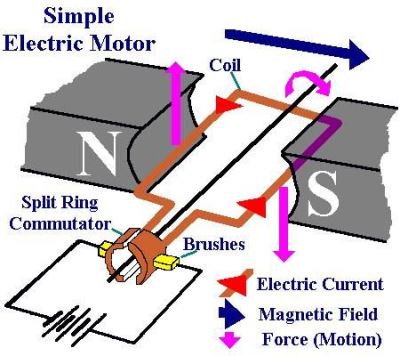
Simple electric motor is a device that converts electrical energy into rotational kinetic energy. A Simple d.c motor consists of a coil of insulated wire between two poles of a magnet as shown in figure below.
The coil ABCD can turn about a fixed axis within magnetic field provided by a strong curved permanent magnet. Electric current enters the coil through split ring P and then leaves the coil through split ring Q. We refers P and Q as the commutators.
The two half rings are insulated from each other and brushes slightly press against the commutator . We then connect the brushes to the battery terminal.
we are assuming that the original position of the coil is at the horizontal position before the current is switched. The current flows in the direction indicated on the diagram when switch is closed. Using Fleming’s left hand rule, side AB experiences an upward force while side CD experiences a downward force.
Since the magnitude of current on both sides is the same, the forces on the sides are equal but opposite. The forces therefore causes the coil rotate in clockwise until it reaches it’s vertical position with side AB up. In this position, the brushes touch the space between the two halves of the split rings cutting off the current flowing hence no force is acting on the sides AB and CD at this position.
Simple Electric motor Coil: Rotation energy
Due to the rotational kinetic energy, the momentum in the coil carries it past this vertical position and the two split rings exchange brushes. We reverse direction of the current through the coil and consequently direction of force on each side of the coil also changes. This process is referred as commutation.
Side AB is now on the right hand side while CD is on the left hand side. Side AB experiences a downward force while CD experience an upward force.
The coil ABCD will continue rotating in the clockwise so long as the current is flowing through it.
If we increase current through the coil, the coil rotates at much high speed. The speed of rotation is thus proportional to the strength of current flowing.
If someone inter-changes terminals of the battery, the direction of the current reverses. Consequently direction of rotation of the coil reverses to the opposite direction.
How to make Simple electric Motor more effective
We can make the D.C motor described above more powerful by adjusting its setup in several ways that include:
winding the coil on a soft iron core so that iron core becomes magnetized. This concentrates it’s magnetic field in the coil which greatly increases the force on the coil.
Increasing the number of turns of the rotating coil. This multiplies the force on the single coil by the number of turns made.
using a stronger magnet that provides more powerful magnetic fields.
Multiplying the number of coils and commutator segments.
Replacing the permanent magnet by an electromagnet. This way, we adjusts strength of the magnetic field as needed.
Contains information related to marketing campaigns of the user. These are shared with Google AdWords / Google Ads when the Google Ads and Google Analytics accounts are linked together.
90 days
__utma
ID used to identify users and sessions
2 years after last activity
__utmt
Used to monitor number of Google Analytics server requests
10 minutes
__utmb
Used to distinguish new sessions and visits. This cookie is set when the GA.js javascript library is loaded and there is no existing __utmb cookie. The cookie is updated every time data is sent to the Google Analytics server.
30 minutes after last activity
__utmc
Used only with old Urchin versions of Google Analytics and not with GA.js. Was used to distinguish between new sessions and visits at the end of a session.
End of session (browser)
__utmz
Contains information about the traffic source or campaign that directed user to the website. The cookie is set when the GA.js javascript is loaded and updated when data is sent to the Google Anaytics server
6 months after last activity
__utmv
Contains custom information set by the web developer via the _setCustomVar method in Google Analytics. This cookie is updated every time new data is sent to the Google Analytics server.
2 years after last activity
__utmx
Used to determine whether a user is included in an A / B or Multivariate test.
18 months
_ga
ID used to identify users
2 years
_gali
Used by Google Analytics to determine which links on a page are being clicked
30 seconds
_ga_
ID used to identify users
2 years
_gid
ID used to identify users for 24 hours after last activity
24 hours
_gat
Used to monitor number of Google Analytics server requests when using Google Tag Manager