Category: Physics

  • Introduction to Quantity of Heat and Capacity.

    Introduction to Quantity of Heat and Capacity.

    Heat is a form of energy that is transferred from one body to another due to a difference in temperature. The study of quantity of heat and heat capacity helps us understand how substances absorb, store, and transfer thermal energy. Quantity of heat refers to the amount of thermal energy gained or lost by a substance, while heat capacity is the measure of the amount of heat required to raise the temperature of a body by one degree Celsius or one Kelvin. These concepts are important in explaining everyday phenomena such as heating water, cooking food, and the functioning of heating systems. Understanding quantity of heat and capacity provides a foundation for studying thermal physics and helps in analyzing how different materials respond to heating and cooling processes.

    Heat is a form of energy that flows from a region of higher temperature to a region of lower temperature.

    When heat is supplied to a substance, two things may happen:

    • The temperature of the substance increases
    • The substance changes its state (for example, melting or boiling)

    Understanding how heat affects matter is important in physics, engineering, and everyday life.


    Heat and Temperature Change

    The rise in temperature of a substance depends on:

    • The mass of the substance
    • The type of material
    • The amount of heat supplied

    This explains why water heats more slowly than metals.


    Heat Capacity

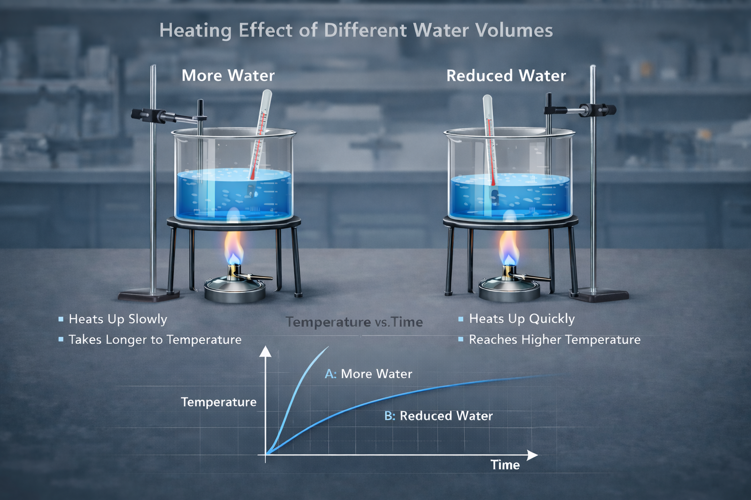
    The figure below illustrates comparing of different capacity of water being heated for sometimes by a bunsen burner. The beakers are identical and the graph shows how their temperature changes with time.

    Definition:
    Heat capacity is the amount of heat required to raise the temperature of a body by 1°C (or 1 K).

    Formula:

    Q = Cθ

    Where:
    Q = heat energy (J)
    C = heat capacity (J K⁻¹)
    θ = temperature change (°C or K)


    Specific Heat Capacity

    Definition:
    Specific heat capacity is the amount of heat required to raise the temperature of 1 kg of a substance by 1 K.

    Formula:

    Q = mcθ

    Where:
    m = mass (kg)
    c = specific heat capacity (J kg⁻¹ K⁻¹)
    θ = temperature change


    Key Concept

    Different materials respond differently to heat:

    • Water has a high specific heat capacity → heats slowly
    • Metals have low specific heat capacity → heat quickly

    Relationship Between Heat Capacity and Specific Heat Capacity

    C = mc

    This means total heat capacity depends on both:

    • Mass
    • Type of material

    Heating Experiment

    Aim:
    To observe how heat affects temperature change in water.

    Procedure:

    1. Measure a fixed volume of water
    2. Record its initial temperature
    3. Heat the water
    4. Record time taken to reach a higher temperature
    5. Repeat using different volumes

    Observation:

    • Larger volume → heats more slowly
    • Smaller volume → heats faster

    Conclusion:
    The quantity of heat required depends on the mass of the substance.


    Worked Examples

    Example 1

    Heat capacity = 460 J K⁻¹
    Temperature change = 45°C − 15°C = 30°C

    Q = Cθ
    Q = 460 × 30
    Q = 13,800 J


    Example 2

    Power = 50 W
    Time = 9 minutes = 540 s

    Q = Pt
    Q = 50 × 540
    Q = 27,000 J


    Example 3

    Mass = 60 g = 0.06 kg
    Specific heat capacity = 390 J kg⁻¹ K⁻¹
    Temperature change = 50°C

    Q = mcθ
    Q = 0.06 × 390 × 50
    Q = 1170 J


    Table of Specific Heat Capacities

    SubstanceValue (J kg⁻¹ K⁻¹)
    Water4200
    Alcohol2400
    Kerosene2200
    Ice2100
    Aluminium900
    Copper390
    Lead130

    Related topics

    watch this video:

  • PRINCIPLES OF MOMENTS: A Complete Guide to Forces, Rotation, and Equilibrium

    PRINCIPLES OF MOMENTS: A Complete Guide to Forces, Rotation, and Equilibrium

    The principle of moments is a fundamental concept in physics that explains how forces cause objects to rotate and how balance is achieved. Whether it is a seesaw, a door, or a bridge, understanding how forces act at different distances from a pivot helps us predict and control motion. By studying moments, we learn not only how to calculate turning effects but also how real-world structures remain stable under various forces. This topic forms an important foundation for mechanics and is widely applied in engineering, construction, and everyday problem-solving.


    🌍 Introduction

    From opening a door to balancing a seesaw, rotation is part of everyday life. The principle of moments helps us understand how and why objects turn, balance, or remain stable under the action of forces.

    This concept is fundamental in physics and engineering, forming the basis for analyzing structures such as bridges, cranes, beams, and even the human body.


    ⚙️ What is a Moment?

    A moment is the turning effect produced by a force about a fixed point called a pivot (or fulcrum).

    👉 The larger the force or the further it is from the pivot, the greater the turning effect.

    Mathematical Definition of principles of moments:

    $$Moment = F \times d$$

    Where:

    • M = Moment (Newton metre, Nm)
    • F = Applied force (Newtons, N)
    • d = Perpendicular distance from pivot to the line of action of the force (metres, m)

    Understanding Perpendicular Distance 📐

    It is not just the distance—it must be the shortest distance from the pivot to the line of action of the force. This is called the perpendicular distance.

    Important:

    • If the force is applied at an angle, you must resolve it or find the perpendicular component.
    • Using the wrong distance is one of the most common mistakes.

    🔄 Direction of Rotation

    Moments can act in two directions:

    • Clockwise moment → turns the object to the right
    • Anticlockwise moment → turns the object to the left

    In calculations:

    • Choose one direction as positive (commonly anticlockwise)
    • The other becomes negative

    ⚖️ Equilibrium of a Body

    A body is said to be in equilibrium when it satisfies two conditions:

    1. Translational Equilibrium

    • No movement in any direction
    • Resultant force = 0

    2. Rotational Equilibrium

    • No turning effect
    • Resultant moment = 0

    📏 Principle of Moments

    This principle combines rotational equilibrium into a simple rule:

    For a body in equilibrium, the sum of clockwise moments about a point equals the sum of anticlockwise moments about the same point.

    Mathematically:

    $$
    \text{Sum of clockwise moments} = \text{Sum of anticlockwise moments}
    $$


    🧠 Why the Principle Works

    If clockwise moments were greater, the object would rotate clockwise.
    If anticlockwise moments were greater, it would rotate anticlockwise.

    👉 Therefore, equality ensures balance.


    🏗️ Real-Life Applications

    The principle of moments is used in:

    • Seesaws → balancing children of different weights
    • Spanners (wrenches) → longer handles produce more turning effect
    • Door handles → placed far from hinges for easier opening
    • Bridges and buildings → ensuring stability under loads
    • Human body → muscles create moments around joints

    🧠 Worked Examples


    Example 1: Finding Distance

    A force of 20 N produces a moment of 100 Nm.

    $$
    d = \frac{100}{20} = 5 , m
    $$

    👉 Distance = 5 m


    Example 2: Multiple Forces on a Beam

    A beam is in equilibrium:

    • Left side: 30 N at 3 m
    • Right side: 10 N at 2 m and another force (F) at 1 m

    $$
    30 \times 3 = (10 \times 2) + F
    $$

    $$
    90 = 20 + F
    $$

    $$
    F = 70N
    $$

    👉 Missing force = 70 N


    Example 5: Taking Moments About Different Points

    A beam has forces acting at different positions. Choosing the pivot wisely simplifies calculations.

    Always take moments about a point where unknown forces act to eliminate them from the equation.


    ⚠️ Common Mistakes to Avoid

    • Using wrong distance (not perpendicular)
    • Ignoring direction of moments
    • Forgetting to include all forces
    • Not choosing a convenient pivot
    • Mixing up units (always use Nm)

    🧩 Advanced Insight

    Moment as Torque

    In more advanced physics, moment is also called torque, especially in rotational dynamics.

    Sign Convention

    You may use:

    • Anticlockwise = positive
    • Clockwise = negative

    This helps when solving complex equations.


    📝 Practice Questions

    1. A force of 18 N acts 2.5 m from a pivot. Find the moment.
    2. A moment of 72 Nm is produced by a force of 12 N. Find the distance.
    3. A beam balances with:
      • 40 N at 3 m (left)
      • F at 6 m (right)
        Find F.
    4. A uniform beam is supported at a pivot. Forces act at different points—determine the unknown force required for equilibrium.
    5. Explain why a long spanner is more effective than a short one.

    🎯 Summary

    • A moment is the turning effect of a force
    • It is calculated using:
      $$
      M = F \times d
      $$
    • A body is in equilibrium when:
      • Resultant force = 0
      • Resultant moment = 0
    • Principle of moments ensures balance:
      • Clockwise moments = Anticlockwise moments

    Final Thought

    Understanding moments allows you to analyze and design systems that remain stable under forces. Whether in engineering, construction, or daily life, this principle is essential for solving real-world problems involving balance and rotation.


    Related topics

    illustrating principles of moments and it's role in a rotating spanner
  • Mass, weight and density

    Mass, weight and density

    Mass, weight and density are fundamental physical quantities that help us understand how matter behaves, how heavy objects are under gravity, and how compact substances are.

    Mass

    Mass of an object is the quantity of matter in it. it remains constant regardless of location or the force of gravity acting on it.

    The SI unit of mass is Kilogram. The symbol for Kilogram is Kg. A kilogram is the mass of a piece of metal that is stored at Sevres, near Paris. It is used as the standard for measuring masses. Sevres is where the International office of weights and Measurements is located.

    Kilogram can be broken into smaller units so that with have a sub-multiples of a kilogram which we can represent with prefixes.

    the table below shows some sub-units of a gram, which is the most common unit of measuring masses. 1000 grams = 1 Kilogram.

    sub unit and symbolequivalent in grams
    picogram (pg)10-12
    nanogram (ng)10-9
    microgram (μg)10-6
    milligrams (mg)10-3
    centigrams(cg)10-2
    decigram (dg)10-1

    The table belows sub units of kilogram as multiples of gram

    sub unitequivalence in gramsequivalent in kilograms
    Decigram(Dg)100.01
    Hectogram(Hg)1000.1
    Kilogram10001.0
    tonne10000001000

    Revision exercise

    1. Convert 0.02 g to milligrams.
    2. Convert 0.75 kg to grams.
    3. Express 250 cg as grams.
    4. what is 0.6 g in centigrams.
    5. Convert 8000 ng to micrograms.
    6. Convert 5 µg to nanograms.

    Weight

    Weight of an object is the pull of gravitational force on it. The pull of the earth, sun and moon on an object is called the force of gravity due to the earth, sun and moon respectively. The SI unit of weight is newton.

    Weight of an object = mass x gravitational force

    in other words: Weight(N) = mass(kg) x g (N/kg)

    Density

    Density of a substance is the mass of a unit cube of the substance, that is; density is mass per unit volume.

    $$Density \ (\rho) =\frac{mass(m)}{volume(V)} $$

    The SI unit of density is kilogram per cubic metre (kgm-3).

    Another common unit of expressing density is grams per cubic centimeters (gcm-3).

    Example problems

    1. Find the mass in Kilograms of an ice cube of side 6cm If the density of ice is 0.92gcm-3 .

    solution

    volume of the cube = 6cm x 6cm x 6cm = 216cm3

    mass = density x volume

    mass = 216cm3 x 0.92gcm-3 = 198.72 g

    $$=\frac{198.72g}{1000g/kg} = 0.19872Kg$$

    2. Find the volume of cork in cubic metre of mass 48g given that density of cork is 0.24gcm-3.

    solution

    $$Volume = \frac{mass}{density} = \frac{48}{0.24gcm^{-3}} = 200cm^3$$

    1 cubic metre = 1000000 cm3

    That is:

    $$1m^3 = 1000000cm^3$$ $$hence \ \text{volume in cubic metre } = \frac{200cm^3}{1000000cm^3} = 0.0002 m^3$$

    Related pages

  • Uniform circular motion with 5 examples

    Uniform circular motion with 5 examples

    Uniform Circular Motion refers to the motion of an object traveling at a constant speed along a circular path. The object’s speed remains constant. However, its velocity is constantly changing. This change occurs due to the continuous change in direction as the object moves along the curve.

    Key characteristics of uniform circular motion includes:

    1. Constant Speed: The object moves with a constant speed along the circle. However, because the direction is always changing, the velocity, which is a vector, changes continuously.
    2. Centripetal Force: An object follows a circular path only if a force acts toward the circle’s center. This is called the centripetal force.

    Consider a particle moving along a circular path when it moves from point A to point B as in figure below.

    illustrating uniform circular motion on a circle

    The reference point OA makes an angle with the line OB that represents the line joining the new position of the object and the center of the circle. The object has covered a distance S along the circle making an arc with θ.

    Angular displacement is the angle swept by a line joining end of an object in a circular path with the center of the path when it moves from one point to another in a circular motion.

    Angles in circular motion are usually expressed in radians θc.

    $$\text{Angle θ in radians}=\frac{arc \ length \ s (AB)}{radius \ r \ (OA)}$$

    That is:

    $$\theta(radians) = \frac{s}{r}$$

    θ(radians)=Sr

    it therefore follows that S = rꝊc

    A radian is defined as an angle subtended at the center of a circle by an arc length equal to the radius of the circle.

    Therefore angle θ subtended by the circumference at the center of a circle of radius r is therefore given by;

    θ=circumferenceradius

    and we can write circumference in terms of π such that:

    2πr=2πc

    We can relate the degrees from 2πc = 360o .

    Problem

    An object traces an arc of length 10.98 while attached to a cord of length 3.2 m that is fixed on a fixed surface on a flat smooth surface. Determine the angular displacement by the object.

    Solution

    We visualize the setup as in figure below:

    from the equation S = rꝊc

    θc=Sr=10.983.2=3.43 radians

    if we can express answers in degrees, then 3.43 radians = 196.52o .

    Practice Question

    An object moves a distance of 80.12 π along a circular path of radius 3.8m. Determine it’s angular displacement.

    Angular velocity for a uniform circular motion

    Angular velocity is defined as the rate of change of angular displacement with time.

    we can shorten the equation by using symbols alone:

    ω=ΔθΔt

    The SI Units of angular velocity is radians per second (rads-1)

    Consider the equation that relates angular displacement in radians with the arc length made by the object:

    θ=Sr

    to get the rate of change of speed, we divide both sides with t as they both represent displacement of the object.

    θt=Srt=1r(St)

    but distance s when divided by time gives velocity. That is;

    v=St

    where v is the linear velocity representing the velocity of the object along the circular path.

    ω=θt

    Hence the equation above becomes:

    hence, the angular velocity can be expressed in terms of linear velocity and radius as show in equation below:

    ω=vr

    similarly, linear velocity can be expressed in terms of angular velocity as v=ωr.

    An object in circular motion has both linear and angular velocity. The time taken to make one complete circle is called the periodic (T) and is given by T= circumstances/speed.

    Let us now consider the time taken for a body to make one complete circle in a circular path. At that one circle, it will have covered the circumference of a circle. The time taken to complete such one revolution is called periodic time (T).

    from the equation :

    time=distancespeed

    and that:

    T=circumferencespeed

    and circumference = 2πr, hence

    T=2πrωr=2πω

    Hence T in the above equation becomes:

    T=2πω

    but

    1T=ω2π

    therefore:

    ω=2πT

    but since:

    1f=T

    ω=2π1f=2πf

    Example question

    A metallic ball is whiled in a horizontal circle making 5 revolution s per second.Determine:

    • Period T
    • angular velocity and
    • linear speed v

    Centripetal force

    Consider on object m held by a cord om positioned at A. The Object is whirled in a circular motion and after some time Δt, the object is at position B. The velocity of the object in linear direction changes from VA to VB. If there was no force acting on the body, the object will not change directions but will go in a straight line. There must be a force that maintain the body at a constant distance distance from the center o.

    Centripetal force Fc refers to the force that keeps a body in circular motion. A body in a circular motion is accelerating and from newton’s second law of motion, there must be a force acting on it to cause acceleration. Centripetal force is usually directed towards the center of the circular path. The Centripetal force is the force responsible for the constant change of direction otherwise the body would naturally follow a straight line if there was no force acting to keep the body in circular motion.

    The value of the centripetal force is derived from newton’s second law of motion which states that: the rate of change of momentum of a body is directly proportional to the resultant force in the direction of force.

    Momentum means mass multiplied by velocity.

    Because velocity of a body in circular motion is changing, it’s momentum must also be changing.

    The newton’s second law can be described as F=ma, where a = acceleration and m is the mass.

    but the acceleration of the body of the body is given by a= v2/r, where v is the linear speed of the object while it is in circular motion. hence

    From definition of angular velocity we had shown that, ω is given by v/r, and hence v=ωr.

    it follows that Fc = m(ωr)2/r = mω2r2/r = mω2r .

    Tension from circular motion

    If a body is attached to a string and swung around on a horizontal circle, the centripetal force that keeps the body in the circular orbit is kept as tension in the string. For the body to remain in circular motion, the centripetal force is equal to the tensional force.

    From the equation Fc = mω2r , it shows that centripetal force is directly proportional to the angular velocity meaning that a larger force will be required to maintain the body in motion if it is swung faster.

    Related Topics

    Share this:

    Customize buttons

    Like this:

    https://widgets.wp.com/likes/?ver=14.2.1#blog_id=249100342&post_id=994&origin=mav.lzf.mybluehost.me&obj_id=249100342-994-69ca06e5d32da&n=1

    Discover more from precisestudy

  • Trigonometric Questions

    Trigonometric Questions

    Trigonometric questions are math problems that involve angles and ratios using trigonometry. They usually test how well you understand relationships between angles and sides of triangles.

    1.Solve the equation 2 cosθ= √3 in the range 0oθ≤360o

    2. Solve for x in the equation -3xsinx=1 in the range 0oθ≤360o

    3. Solve for x in the equation sin2x = 0.25 for 0oθ≤360o giving your answer in πc

    4.$$\text{Given that } tan \theta = \frac{sin \theta}{cos \theta}$$

    5. solve the equation 2 sinθ = cosθ in the range 0oθ≤360o to the nearest whole number

    6. Calculate without using log table:

    $$\frac{sin 225^o \times cos360^o \times tan 30^o}{sin 120^o \times cos 315^o}$$

    7.Triangle ABC is inscribed in a circle as in figure below. AB = 9.2cm, AC = 7.9 and BC=4.4cm

    Trigonometric question

    Find: (a) Angle A (2 marks)

    (b) The radius of the circle correct to 1 d.p (2 marks)

    Related pages

  • focal length by displacement

    focal length by displacement

    Focal length by displacement is a method of estimating focal length of a lens where we change the position of a lens and observe the image formed on a screen while distance between object and the lenses is unchanged.

    Ensure you have the following apparatus:

    Lens Holder
    The screen
    screen used in an experiment to determine focal length of lens by displacement method
    cross wires
    source of light in an experiment to find focal length of a lens by displacement method
    bulb as a source of light
    candle in an experiment to determine focal length of a lens by displacement method
    candle as a source of light

    metre rule

    Procedure to estimate focal length by displacement

    • Estimate the focal length of the lens by focusing a distance object
    • Set the apparatus as in figure below ensuring that the distance between the object and the screen is more than 4f where f is the focal length estimated above.
    • Obtain the image of the illuminated object on the screen when the lens is at position L1
    • move the lens to position L2 where another clear but diminished image is formed on the screen as Without changing the position of the object on the screen, shown below.
    • measure u and v for position L1 and the new distance u1 and v1 for position L2.
    • Determine the displacement d .
    Deriving the displacement formular

    from the diagram above, the distance between the point object and the screen is s. from the diagram, it is shown that the distance s is given by u+v.

    Advertisement

    i. e. s = u+v ………………………………..(1)

    we get the distance between new and original position of the lens by use of expressions:

    d=u’- u where u’ is the new object distance and u the original object distance

    d can also be obtained from v-v’ which is the original image distance and image distance when the lens is displaced by distance d.

    i.e d=u’-u and d = v-v’

    but u’=v and v’=u

    and therefore:

    d=v-u………………………………….(2)

    adding (1) and (2);

    hence s+ d= u + v + v –u

    and so: s + d = 2v and hence;

    $$V = \frac{s+d}{2}$$

    similarly we can subtract equation 2 from 1 as shown:

    hence s- d = u + v –v + u

    therefore : s- d = 2u and hence;

    $$u = \frac{s-d}{2}$$

    from the lens formulae:

    $$\frac{1}{f} = \frac{1}{u}+\frac{1}{v}$$

    we can substitute values of u and v in terms of s and d as obtained in the expressions above. And hence;

    $$\frac{1}{f} = \frac{1}{\frac{s-d}{2}}+ \frac{1}{\frac{s+d}{2}}$$

    the above equation can be simplified into:

    $$\frac{1}{f} = \frac{2}{s-d}+\frac{2}{s+d}$$

    finding the lcm of the denominator, we obtain;

    1f=2(s+d)+2(s−d)(s−d)(s+d)=2s+2d+2s−2ds2−d2

    $$\frac{1}{f} = \frac{2(s+d)+2(s-d)}{(s-d)(s+d)}$$

    and simplifying the above equation in the numerator:

    $$\frac{1}{f} = \frac{4s}{s^2 – d^2}$$

    and finding the reciprocal so that we can get f;

    $$f = \frac{s^2-d^2}{4s}$$

    f=s2–d24s

    from the above equation: s2-d2 = 4fs

    a plot of s2-d2 against s results to a straight line through the origin with a slope equal to 4f.

    different values of s are obtained by changing distance between the object and the screen and then calculating the corresponding distance d.

    The two positions L1 and Lthat represents different positions of the lens are known as the conjugate points.

    Related topics

  • Estimating focal length of a lens

    Estimating focal length of a lens

    Estimating the focal length of a lens is a fundamental experiment in optics. It helps learners understand how lenses form images and bend light. Focal length is the distance between the optical center of a lens and its principal focus. Focal length determines how strongly the lens converges or diverges light rays. In this topic, students explore practical methods of measuring focal length using simple laboratory setups. This includes forming sharp images of distant objects or using object–image distance measurements. Through this investigation, learners develop essential skills in observation, measurement, and application of lens formulas, building a strong foundation for further studies in physics and optical instruments.

    We can always determine the focal length of the given lenses by applying various methods of estimating focal length of a lens.

    This methods may includes:

    • Focusing on a distance object
    • lens formula experiments
    • Using non-parallax method
    • Using an illuminated object
    • Displacement method

    Page Contents

    Focusing a distance object to estimate focal length

    We arrange the white screen, convex lens on a lens holder and ruler such that rays of light from a distance object are incident on a lens that is close to the white screen.

    See the diagram below

    estimating focal length by focusing a distance object

    We adjust the lens position to and fro until we obtain a sharp image of a distance object on the screen.

    Distance object means an object that is at large distance relative to the focal length of the lens. For instance an object 30 metre from a lens whose focal length is 21cm is a distance object. We note that, object position is many times longer compared to the focal length of the lens.

    Distance between the lens and screen where the sharp image of a distance object is formed is considered to be the focal length of the lens. The area occupied by the image is the focal plane of the lens.

    The estimated focal length is not exact but can be 2 cm plus or minus the real focal length.

    This method of estimating focal length depends on the fact that parallel rays from infinity converges at the focal point on the screen.

    Non-parallax method of estimating focal length

    Parallax is a displacement or difference in the apparent position of an object viewed along two different lines of sight and is measured by the angle of inclination between those two lines.

    Non-parallax is therefore when there is no difference in apparent position when an object is viewed along two different lines of sight.

    An optical pin fixed on a cork that is supported by a clamp is placed above a lens that is on the mirror as shown below. The cork is such that it slides up and down the glass rod. see the diagram below.

    estimating focal length by use parallax method

    Adjust height of the pin until it’s image is seen on the mirror.

    The position of the pin is adjusted until the image from the mirror and the object pin seems to be moving together when you move your eyes.

    Distance between lens and the pin when there is no parallax between image and object is the focal length of the lens.

    Non-parallax: Using an illuminated object to estimate focal length

    A bulb is placed behind a hole with a cross wire on a cardboard so as shown in figure below. A lens on a lens holder is placed between a mirror and the cardboard.

    The cardboard together with the source of light is moved along the metre rule until a sharp image of the cross wire is formed along the cross wire object as shown. The figure shows two rays emerging from the point source towards the mirror through the lens

    The lengths f gives the focal length of the lens.

    Explanation

    The ray striking the mirror are reflected back along the same paths of the incidence so that the image of the source coincides with the source itself. This image can be received on a screen placed at the same position as the source as shown.

    showing a cross wire image coinciding with it's own image on the same plane

    If both lens and the mirror are perfectly vertical or parallel , image coincides perfectly with the illuminated crosswire. This makes it hard to see when Estimating focal length.

    It is therefore necessary to tilt either the lens or the mirror a little so that the image can be mapped besides the hole.

    In the above arrangement, the object pin is moved towards the lens or away until it coincides with it’s inverted image. This occurs when the pinhead is vertically above the center of the lens.

    At a point where the object and the image perfectly coincides, there is no relative motion between them. As the eye is moved perpendicular to them, they all move together as one.

    The distance between the pin and the lens is then measured as the focal length of the lense.

    NB: Focal length increases as thickness of the lens decreases. This is because thick lenses refracts and deviates light more sharply than a thin lenses. Therefore, rays emerging from thick lens tends to converge earlier because because of the sharp bending in the lens.

    Related topics

  • Focal length from lens formula

    Focal length from lens formula

    Determining Focal length from lens formula involves doing experiments to find different positions of image while adjusting object positions.

    Focal length of a lens can be determined by investigating relationship between image distance and object distance by obtaining image distances from varying object distances.

    The mirror formula describes the relationship that exists between the focal length, image distance and the object distance. Using the mirror formula derived earlier, We describe the experiment here and explains how to extract the the focal length from the relationship.

    The mirror describes the relationship that exists between the focal length, image distance and the object distance.

    The unknown Focal length of a lens can be determined experimentally by use of lens formula derived earlier. We describe the experiment here and explains how to extract the the focal length from the relationship.

    We draw the graph of the of reciprocal values of image distance against the reciprocal values of object distance. The intercept of the graph is used to estimate the focal length of the lens used.

    Apparatus

    • Metre rule
    • lens and a lens holder
    • source of light
    • screen
    • cardboard with a cross wire

    procedure

    • set the apparatus as shown
    lens screen and object arrangement to determine focal length by use of lenses formula
    • You place the object at the zero centimeter mark
    • set the object distance by placing the lens at a reasonable distance from the object like 80cm from the object.
    • Adjust the screen to observe a sharp image on the screen.
    • Record a distance between the screen and the lens where you spot a sharp image on the screen is the image distance.
    • Record the image and the object distance
    • Reduce the object distance u by about 5 cm then adjust the screen until you see another sharp image on the screen.
    • reduce the distances distance again by 5 cm and repeat the procedure above.
    • Fill the table as shown below
    a table showing variation of image against variation of object distance

    From the data obtain a graph of 1/u against 1/v by plotting.

    A typical graph will be as shown:

    The graph of 1/v against 1/u used to determine focal length from lens formula

    Graphical analysis of the Lens formula

    The lens formula is stated as:

    1f=1u+1v

    From the above formula, one can see that the sum of reciprocals of the image length from the lens and the reciprocal of the image distances equals reciprocal of the focal length.

    At the (1/v) intercept the value of (1/u)= 0. The lens formular becomes:

    1f=0+1v

    We eliminated 1/u from the formula after it become zero such that:

    1f=1v

    The value of f-1 (1/f) is equal to 1/v meaning that we can approximate the reciprocal of f as the reciprocal of the image distance v read at the intercept.

    At the (1/u) intercept, the the value of (1/v) =0. The lens formula becomes

    1f=1u+0

    The formular is reduced to be as follow:

    1f=1u

    Determining the Focal length from lens formula

    as a process of Determining Focal length from lens formula, from the graph, we can deduce that 1/u and 1/v gives reciprocal of the Focal length 1/f at the intercepts.

    we can get two values of f from the 1/v and 1/u intercepts such that:

    f1=(1V)−1andf2=(1U)−1

    The focal length f is the average of f1 and f2 such that:

    f=f1+f22

    Question for practice

    The table below shows values of object distance u and corresponding value of image distances a for a convex lens.

    object distance u(cm)101520253035
    image distance v(cm)40.017.113.111.810.910.4

    a table showing relationship between image distance and object distance

    plot a suitable graph and from the graph determine the focal length of the lens.

    References:

    • Secondary Physics Student’s Book Four. 3rd ed., Kenya Literature Bureau, 2012. pp. 1-42.
    • Abbot A. F. (1980), Ordinary Level Physics, 3rd Edition, Heinemann Books International,
      London.
    • Nelkon M. and Parker P., (1987), Advanced Level Physics, Heinemann Educational
      Publishers, London.
    • Tom D., and Heather K. Cambridge IGCSE Physics. 3rd ed., Hodder Education, 2018, https://doi.org/978 1 4441 76421. pp. 106-142.

    Share this:

  • A concise Introduction to thin lenses

    Table of Contents

    Introduction to thin lenses involves general description about properties of thin lenses.

    A lens can be defined as a piece of curved glass or plastic that makes things look larger, smaller or clearer when you look through it.

    In human eye, one component is a lens and so we can also define lens as the transparent part of the eye, behind the pupil, that focuses light so that you can see clearly.

    The idea behind lens operations is that when a light ray passes from air which is more optically denser than the lens material, it is refracted.

    When many rays passes through the lens, they all refracted the same way and so they meet at a common point. Sometimes they don’t meet but instead they are scattered after refraction but they are seemed to be spreading from a common point.

    Lenses are usually made of glass, transparent plastic or perspex.

    common application of lenses includes cameras, spectacles,telescopes, microscopes, film projectors and the human eye.

    A thin lens means a lens whose thickness is negligible compared to the radius of curvature of the lens surfaces.

    eye glasses

    Types of thin lenses

    The basic two types of lenses are convex and concave lenses.

    Convex lenses are also called converging lenses as they cause the rays that passes through it to meet at a point. Convex lenses are thickest at the middle and they thin in as you move towards their edge.

    In this lesson we will be talking about biconvex lenses meaning that it is symmetrical if we cut it long it’s edges. Both sides of it’s services at the center are bulging outwards and the edges are curved inwards uniformly on both sides.see the figure below

    Bi convex lens
    showing symmetrical in bi-convex lens

    Concave lenses are also called diverging lenses as they cause the rays passing through them to be spreading from a common pint. Concave lenses are thinnest at the middle and they they become thicker as you move towards the edges.

    Illustrating concave lens
    illustrating bi-concave lens

    There are variations of convex and concave lenses as illustrated in figures below

    plano convex lens
    convex meniscus lens
    plano concave lens
    concave meniscus lens

    Effects of lenses on Parallel rays of light

    A cardboard with parallel slits is placed between the mirror and a bi-convex lens as in figure below

    The mirror is set such that it reflects the sun rays so that the rays passes through the slits before they reach the lens.

    After making observations, the bi-convex lens is replaced with a concave lens

    Observation

    when a convex lens is used, the rays are converged at a point on the paper and then diverge as they continue as shown.

    illustrations of parallel rays as they pass through a bi-convex lens

    When concave lens is used , the rays diverge as if they were from the focal point in front of the lens as shown.

    illustrations of parallel rays as they pass through a biconcave lens

    Investigating convergence and divergence of light by thin lenses using a ray box

    A ray box acts as a source of parallel beam. A spot light can also be used.

    A parallel beam is directed incident to the the lens as shown

    Parallel rays of light incident to a convex lens

    A white paper is placed on the other side of the lens and it’s position adjusted until a sharp point is observed.

    observation

    When a convex lens is used, the rays are converged at a point on the paper and then diverges as they continue as shown below

    Parallel beam after passing through a converging lens

    If convex lens was replaced with concave (diverging) lens, the rays will be observed diverging as if they are coming from a point on the other side of the lens. see the diagram below.

    Parallel beam incident to diverging lens

    Explanations

    Light is usually refracted when it passes through a glass prism. A lens can be considered as an assembly of many tiny prisms where each prism refracts light as in figure below.

    Illustrations of bi-convex lens as an assembly of prisms

    Please note that, the middle part of the prism is like a rectangular glass prism and a ray that is incident to it at a perpendicular angle passes through without being refracted. As we may see in other lessons, a ray of light that passes normally through the geometrical center of the lens, passes through undeviated.

    The figure below shows representation of concave lens as an assembly of prisms.

    illustrations of concave lens as an assembly of prisms

    conclusions

    Rays of light that passes through a lens converges at a fixed point from the lens if the lens is a converging lens or diverge from a common imaginary point if the lens is a diverging lens.

    The point at which the rays emerging from the lens converge or seems to diverge from is referred to as the principal focus.

    A convex lens has a real principal focus while a concave lens has a virtual (imaginary) principal focus.


    References:
    • Secondary Physics Student’s Book Four. 3rd ed., Kenya Literature Bureau, 2012. pp. 1-42.
    • Abbot A. F. (1980), Ordinary Level Physics, 3rd Edition, Heinemann Books International,
      London.
    • Nelkon M. and Parker P., (1987), Advanced Level Physics, Heinemann Educational
      Publishers, London.
    • Tom D., and Heather K. Cambridge IGCSE Physics. 3rd ed., Hodder Education, 2018, https://doi.org/978 1 4441 76421. pp. 106-142.
  • Questions involving pressure in Physics

    Questions involving pressure in Physics

    Questions involving pressure are physics questions that test your understanding of the concept of pressure, how it is calculated, and how it applies in solids, liquids, and gases.

    They may involve:

    • Calculating pressure using formulas
    • Explaining real-life applications
    • Understanding liquid pressure
    • Understanding atmospheric pressure
    • Applying Blaise Pascal’s Principle

    Here are questions involving pressure


    1. The figure below shows Hare’s apparatus used for comparing liquid densities.
    Questions involving pressure-the hare's apparatus

    Use the information given in the above diagram to calculate the density of liquid x given that density of water is 1000kgm-3        (2mks)

    answer

    $$ \delta_w g h_w = \delta_wgh_x $$ $$delta_x = \frac{1000 \times 30}{25} = 1200kgm^{-3}$$ $$1000 \times 30 = \delta_x \times 25 \ $$

    2. Figure 3 below shows a student drinking a soda using a straw.

    drinking from a straw in a question involving pressure from the atmosphere

    Figure 3

    . Explain why the soda rises up a straw when the student sucked on it.                 (2mks)

    answer

    Sucking decreases pressure inside the straw; and the greater atmospheric pressure pushes the soda up.


    3. Using the idea of particles explain why the pressure inside the tyre increases when the tyre is pumped up     (2mks)

    answer

    When more air is pumped into the tyre the number of particles colliding with the walls increases; They increase the rate of change in momentum, hence the force per unit area increases;       


    4. Explain why a hole in a ship near the bottom is more dangerous than one nearer the surface.(2mks)

    answer

    Pressure in liquids increases with depth ; hence water will enter the ship at a higher rate making it to sink


    5. The atmospheric pressure at the foot of Mt. Longonot is 760mm of mercury while at the peak of the mountain, the atmospheric pressure is 580mm of mercury. Given that the density of mercury is 13600Kg/m3, Calculate the height of the mountain (density of air = 1.3 Kg/m3.) (3mks)

    Answer

    Pressure difference = 760 – 580 = 180mmHg;
    Pressure due to liquid column = ρgh – 0.18 x 10 x 13600 = 1.3 x h x 10;
    H = 1883.1m;

    6. Use fig. 3 below to answer questions 3 and 4.


    Three identical tubes containing mercury were inverted as shown.

    Explain the effect on the level of mercury in tube A if region X is filled with some air. (2 mks)

    answer

    The vertical height of mercury would be less than 76 cm. The trapped air would exert pressure on the column of mercury.

    Indicate on the diagram above the levels of mercury in tube B and C. (1 mk)

    answer


      Related topics