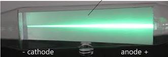
Cathode rays are streams of negatively charged particles, or electrons, which are accelerated from a cathode to the anode within a vacuum tube by an electrical potential.
These rays travel to the positively charged anode, creating a visible beam. They are also known as electron beams and were instrumental in the discovery of the electron.
Before the electrons are accelerated, they must be extracted from a atoms and be on the surface. Electrons are first extracted from from the nuclei to a metal surface when the metal is heated. The heat energy raises the energy of an electron. This enables it to break loose from the force of attraction of the nuclei. This process where electrons are emitted to the surface is known as thermionic emission.
When a material is heated, its atoms vibrate more vigorously. This thermal energy can be transferred to the electrons in the material. If the temperature is high enough, some electrons gain enough energy to overcome the work function of the material. Work function is the minimum energy needed for an electron to escape from the surface of the material. It escapes into the vacuum or surrounding environment.
Thermionic Emission for cathode rays
In thermionic emission, a cathode is heated from low voltage supply so that electrons can be extracted to the surface. Another higher voltage is then used to accelerates the electrons produced towards an anode. A typical setup used for thermionic is as shown below.
A cathode which is inside the evacuated glass tube is made with mixture of barium oxides and strontium oxide. The resulting metal oxide has a low work function. This means that the minimum energy required to remove an electron from its atom to the surface is low.
In the setup a low voltage of about 6V drives a current through the heating filament which then heats the cathode
Initially the reading on the milliammeter(mA) is zero. When the heater circuit is switched on, some current is observed on the milliammeter after some time. This means that the current circuit between the cathode and the anode has been completed. There is a wide gap between the anode and the cathode. However, when the heater current is switched on, the heater circuit is complete in the gap.
This is because cathode the electrons produced by the cathode are able to move to the anode across the gap. How do they do that?
The hot cathode emits electrons which are then attracted to to the anode due to the 12V accelerating potential. This acceleration ensures electrons are able to move across the gap hence making the circuit complete. This setup allows us to observe thermionic emission. It helps explain the cathode rays inside the evacuated glass tube we call a cathode ray tube.
Production of cathode rays
Cathode rays are usually produced in cathode ray tube (CRT).
A cathode ray tube
Electrons produced at the cathode by thermionic emission are accelerated towards a fluorescent screen. This fluorescent screen connected to the anode which is connected to the positive terminal of an extra high tension (E.H.T) source. When cathode rays are stopped by the fluorescent screen, the kinetic energy of the cathode causes the screen to glow.
The reason the tube is evacuated is to ensure electrons do not collide with gaseous particles before reaching the screen. If electrons collides with other particles, ionization of the gas in the tube occurs. This is found to be causing different observations from the one intended. Collision with some other particles can cause electrons to loose their energy and probably not able to reach the screen. The movement of cathode rays in a cathode ray tube is illustrated in the table figure below:
Questions
What is thermionic emission
Illustrate production of cathode rays using a suitable diagram.
Explain why it is important for a cathode ray tube to be evacuated.
The High voltage transmission is used to carry electricity over long distances with minimized power loss. When electricity is transmitted at high voltages (e.g 110 kV, 220 kV, or even 765 kV). less energy is lost as heat due to resistance in the wires. In the high voltage transmission, Power stations usually generate an alternating current a.c at a voltage between 11KV and 25KV. The power generated is then stepped up to 132KV-400KV so that it can be transmitted to long distances from the power station. The electrical power is usually transmitted over long distance to substations where the voltage is stepped down to 11KV. From the substations, power is distributed to consumers . This is after being stepped down to the consumable levels according to the needs of each consumer. Consumers can be heavy industry that may need over 30KV. light industry that may need over 10KV or domestic homes that may need only 240V.
Dangers of High Voltage Transmission
risk of electric shock incase poles collapse or cables hangs too low
The cables can cause fire on nearby structure and vegetation when cables are too loose
Because of the high voltage, there is strong electric fields that can interfere with health of people exposed to such fields.
During thunder and lightening, the cables can conduct excess charges from the lighting causing danger to houses and machines using electricity.
during strong wind, the cables can come into contact with each other causing fire.
Power losses During High Voltage Transmission
Given that; I=current flowing, V=voltage supplied and R =electrical resistance in the High voltage transmission cables :
Power dissipated in a circuit is given by ; P=VI
From ohm’s law V = IR. Hence, P = (IR)I = I2R
This means that for a given resistance in a circuit, when the current is high , the power loss is large and when the current is low, the power loss is small.
Power loss in High voltage transmission is therefore low when it is transmitted at high voltage and low current.
To attain high voltage and low current, output voltage from power station is stepped up for long distance transmission. This is done to minimize power losses in transmission cables. We do this is ensuring the current is as low as possible with the same power output.
Since long distances are involved, the transmission cables are thick and made from very good conductors of electric current to ensure resistance is kept to minimum.
aluminum cables are preferred in high voltage transmission because :
It is a good conductor of electric current
It can be obtained cheaply
It is light
Example problem
The resistance a of power transmitting cable is 10Ω and is used to transmit 11Kv at 1A current. If this voltage is stepped-up to 16kv by a transformer, determine the power loss.
solution
assuming the transmission is 100% efficient:
power input = power output
VpIp = VsIs
11000 x 1 = 160 000 x Is
= 0.069A
power lost = I2R = (0.069)2 x 10 = 0.048W
If there was no stepping up of the voltage the power loss would be:
power loss = (1.0)2 x 10 = 10W which is actually 200 times wastage compared to power calculated above.
Practice Question on the high voltage transmission
A generator produces 750kW at a voltage of 15kV. For high voltage transmission, This voltage is stepped up to 125kV .It is to be transmitted through cables of resistance 0f 500 Ω to a step-down transformer in a substation. Assuming that both transformers are 100% efficient:
(a) calculate:
(I)The current produced by the generator
(ii) the current that flows through the transmission cables
(iii) the voltage drop across the transmission cables
(iii) power lost during transmission
(iv) power that reaches substation
solution
(I)
power input = Voltage in primary coil x Current in the primary coil
that is: power input = Vp x Ip
Current in primary Ip will therefore be given us:
Ip=PVp
and substituting for the values of power and primary voltage we have:
Ip=750∗1000w15000V=50A
so the current produced originally in the primary coil is 50.0A
(ii)
At the step-up transformer;
power input = power output (no power is lost because the transformer is 100% efficient)
that is: power in primary generator = power after step up
Vp x Ip = Vs x Is
15000V x 50A = 125000xIs
Is=15000V∗50A125∗1000=6A
Power losses during high Voltage transmission
Power losses is common during high voltage transmission . High voltage power transmission involves moving electrical power from the source where it is being generated to consumer premises (sometimes hundreds of kilometers way) where it need to be used.
In high voltage power transmission, power loss during transmission is minimized by transporting electrical power in high voltage but at a small current. High voltage transmission involves transporting electrical power over long distances through electrical cables. From electricity topics, we learn that conductors have some resistance to the flow of currents. The resistance in a conductor is proportional to the length of the conductor. Power losses during transmission is caused by the heating effect that results from resistance of current in the conductor. Because the distance involved can be hundreds of kilometers, power losses can be significant.
Power losses during transmission
we determines power dissipated in a circuit from the relation:
Power P = VI.
Where V is voltage across the circuit and I is the current flowing in the circuit.
From Ohms law of electric current; V= IR. Where R is the resistance in the circuit.
Therefore, Power = (IR)I = I2R.
From the equations above, you can see that power loss can be high when current is high for a given resistance value in the conductor.
Because power is constant, the idea of transmitting power efficiently is by increasing its voltage. Increasing voltage ensures reduced current for the same power source. The best way to minimize power loss during transmission is to transmit at very high voltage. It should also be done at the smallest current possible. We usually step up the voltage produced at the source to high voltage values. This adjustment brings the current closer to zero as much as possible.
power providers can also reduce electrical resistance in transmission cables by choosing cable with thick diameter but one that is a good conductor of electricity.
Power providers prefers aluminum as thee best choice for transmission cables since it is a good conductor, cheap to obtain and it is not heavy. An alternating current power source is the one preferred in high voltage transmission because it is can easily stepped up and down when needed.
Example Problems
A power company uses a power cable of with overall resistance of 5000Ω to transmit 10Kv at a current of 0.8A. They use a transformer to step up this voltage to 25KV by a transformer, determine:
(i) power loss expected if there was no step-up
(ii) power loss expectations after step-up
(iii) percentage ratio between power power lost before step-up to power loss after step-up
solution
(i) Power = I2R.
hence power loss when voltage is not stepped up=(0.8)R x 5000=3200 watts.
(ii) Assuming that there is no power loss in the transformer; After stepping up the following equation applies:
power before step-up = power after step-up.
power before step-up is the power fed into primary coil of the transformer;
Using the transformer equation; Power in primary coil = power in the secondary coil.
That is; VpIp = VsIs
substituting in the equation to get the current after stepping up we have:
10000v x 0.8A = 25000v x Is
and hence;
Is=10000V∗0.8A25000= 0.32A
stepping up has reduced current flow from 0.8A to 0.32A
power lost due to this new current will be:
Power lost = (0.32)2 * 5000 = 512 watts
(iii) The ratio of power lost before stepping up to power lost after stepping up will be
powerratio=3200watts512watts∗100= 625%
from the above working, one can see that power loss has been reduced by 625% when power is stepped up from 10KV to 25KV. This proves to us that stepping up power to reduce current contributes to reduction of power loss in a big way.
Question for practice
A generator produces 700kW at a voltage of 15kV. The voltage is stepped up to 125KV and the power transmitted through the cables of resistance 300Ω to a step-down transformer in a sub-station. Assuming that both transformers are 100% efficient:
(a) calculate:
(i) The current produced by the generator
(ii) The current that flows through the transmission cables
Current and electricity are core topics in physics, encompassing electric current, circuits, resistance, and the behavior of electrons. Key areas that can be tested include the nature of electric current. Another key area is Ohm’s law, Series and parallel circuits, the heating effect of electric current among others
Questions
Figure 1 shows four identical bulbs connected to a 15 volt battery whose internal is negligible.
Figure 1
Determine the reading of the voltmeter V. (2 marks).
2. Figure 14 shows a circuit in which a battery. a switch , a bulb, resistor P, a variable resistor Q. a voltmeter V and two ammeters A1 and A2 of negligible resistance are connected.
P has a resistance of 10 Ω. When the switch is closed A1 and A2 reads 0.10 A and the voltmeter reads 1.5 V.
(a) Determine;.
      (i) the current passing through P;     (3 marks).
----------------------------------------------------------------------------------------------------------------------------------------------------------------------------------------------------------------------------------------------------------------------------------------------------------------------------------------------------------------------------------
       (ii) the resistance of the bulb               (2 marks).
----------------------------------------------------------------------------------------------------------------------------------------------------------------------------------------------------------------------------------------------------------------------------------------------------------------------------------------------------------------------------------
(b) The variable resistor Q is now adjusted so that a larger current flows through A2 .
     (i) State how this will affect the resistance of the bulb   (1 mark)
----------------------------------------------------------------------------------------------------------------------------------------------------

      (ii) Explain your answer in (b)(i).                        (3 marks)
------------------------------------------------------------------------.
------------------------------------------------------------------------.
------------------------------------------------------------------------.
------------------------------------------------------------------------.
------------------------------------------------------------------------.
------------------------------------------------------------------------.
------------------------------------------------------------------------.

(c) A house has one 100W bulb, two 60W bulbs and one 30W bulb. Determine the cost of having all the bulbs switched on for 70 hours,. given that the cost of electricity is 40 cents per kilowatt hour.    (3 marks).
3. (a) Define current stating its S.I units. (2 mark)
 (b) A battery circulates charges round a circuit for 1.5 minutes. If the current is held at 2.5 Amperes,   what quantity of charge passes though the wire? (2 marks)
------------------------------------------------------------------------------------------------------------------------------------------------------------------------------------------------------------------------------
4. Figure 2 shows arrangement of three capacities of 10µF, 2µF and 5µF.
Determine the effective capacitance. (3 marks)
5.(a) Figure 8 shows a graph of potential difference V (volts) against a current I(amperes) for a certain device.
From the graph:
(i) State with a reason whether or not the device obeys ohms law. (2 marks)
(ii) determine the resistance of the device at ;
(I) I =1.5 A (2 marks)
(II) I = 3.5 A (2 marks)
(iii) From the results obtained in (ii) state how the resistance of the device varies as the current increases. ( 1 mark)
(iv) State the cause of this variation in resistance. (1 mark)
5(b) Three identical dry cells each of e.m.f 1.6 V are connected in series to a resistor of 11.4 ohms. A current of 0.32A flows in the circuit. Determine:
(i) The total e.m.f of the cells (1 mark)
(ii) The internal resistance of each cell; (3 marks)
6. Figure 6 below shows an electric generator. The points P and Q are connected to a cathode ray oscilloscope (CRO).
Figure 6
Sketch on the axes provided the graph of the voltage output as seen on the CRO, given that when t=0 the coil is at the position shown in the figure. (2 marks).
7. A 60 W bulb is used continuously for 36 hours. Determine the energy consumed. Give your answer in kilowatt hour (kWh). (3 marks)
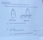
8. Figure 8 shows the cross-section of a dry cell. Use the information on the figure to answer questions 4 and 5.
Figure 8
Name the parts labelled A and B. (2 marks)
8 (b) State the use of the manganese(IV) oxide in the cell. (1 mark).
9. A 4 ohms resistor is connected in series to a battery of e.m.f 6.0 V and negligible internal . Determine the power dissipated by the resistor (2 marks)
10. State the reason why electrical power is transmitted over long distances at very high voltages .(1 mark)
Electric current and potential difference represents two phenomenon that depends on each other to exist in electricity concepts. An electric current is the rate of flow of charge through a conductor. Current flows when there is a potential difference between two points in a conductor. Electric current is measured in amperes by an instrument called ammeter. An ammeter is an electrical instrument used to measure the current flowing through a circuit. The ammeter is designed to be connected in series with the circuit. This ensures that the current flows through the ammeter, allowing it to accurately measure the amount of electrical current.
There are two types of ammeters:
Instruments used in experiments of electric current and potential difference
Analog Ammeter: This uses a needle or pointer to indicate the current on a scale.
The figure below shows an analog ammeter ammeter common in school laboratories.
An ammeter
2. Digital Ammeter: This displays the current measurement on a digital screen. It provides a digital readout of the electrical current. Digital ammeter allows one to choose a scale of measurement in amperes (A), milli-amperes (mA), or micro-amperes (µA). It uses a numerical display rather than a moving needle or pointer.
A Digital ammeter
Electric current flows between two points in a closed path due to a potential difference between those two points. Sometimes the flowing current can be too small to me measured by an ammeter. A more sensitive instrument may therefore be required to measure small currents.
A millimeter is an instrument used to measure current in terms of one in thousand of an ampere. A milliammeter measures current in terms of milli-amperes.
$$1 \ milli-ampere(MA) = \frac{1}{1000} Amperes$$
Much smaller currents can be measured by a micro- ammeter. A micro-ammeter measures current in terms of micro-ampere.
An ammeter has very low electrical resistance. Therefore it is connected in series with the instrument whose current passing through need to be measured. When connecting an ammeter in the circuit, ensure it is done correctly. The correct procedure is such that current enters the ammeter through positive terminal and exits through the negative terminal. If connected such that convectional current enters through negative terminal, the ammeter may get damaged.
The figure below shows the ammeter connected in series with the bulb. The convectional current flowing through the bulb also flows through the ammeter.
correct ammeter connection
The figure below shows wrong ammeter connection. Note that the positive terminal of the ammeter is connected to the negative terminal of the cell.
wrong ammeter connection
Before connecting the ammeter in a circuit, confirm that it’s pointer is at zero mark on the scale. Otherwise, use the zero adjusting screw to move it to the correct position. Most of ammeters has two scales. An appropriate scale should be selected to safeguard the coil from damaged if current passing exceeds its capacity. For example an ammeter can have a scale of (0-3)A or (0-5)A. The figure below shows an ammeter dashboard with two scales; (0-5)A and (0-2.5)A.
If a scale of (0 – 5) A is selected, the meter can read up to 5 A. With such a scale, 10 divisions represents 1.0 A. For a (0-2.5) A scale, ten divisions will represent 0.5 A meaning each division is 0.05 A. From the diagram, the reading on the ammeter is 2.45 A while reading (0-5) A or 1.225 while reading the (0 -2.5) A.
Electric current and potential difference: using a voltmeter
while investigating electric current and potential difference, we need to measure potential difference across various components in the circuit. A voltmeter is always connected across the device (parallel to the device) which the voltage is to be measured. The figure below shows voltmeter connected across the bulb in parallel arrangement.
Voltmeter is connected in series because it is an instrument with high resistance to the flow of current. Therefore, It takes no current from the component across which the voltage is to be measured.
The positive terminal of the voltmeter is connected to the point where convectional current is entering a component. Its negative terminal is connected to the point where the current is leaving the component.
One should ensure that the pointer is exactly on the zero mark before connecting the voltmeter. If pointer is not at zero, the pointer should be adjusted to zero by the screw.
The table of tangents holds values for every acute angle from 0o to 90o. Each angle has a unique tangent ratio. We get this ratio when two lines meet to make the angle.
Every combination of opposite and adjacent lines that makes a right angled triangle has a unique angle which they make.
If we know the acute angle in a right angled triangle, we can use tables of tangents. This helps us find its corresponding tangent ratio. Similarly, if we know the angle and just one side, we can find the angle’s ratio. Then, we use the tangent relationship to find the other side.
The table of tangents consists of angles from 0o to 90o. We express these angles in 4 significant figures and record their values in a table. All we need to do as mathematician is get a certain angle and find it’s corresponding ratio from the tables.
We expresses angles in the table of tangents in degrees, points of degrees and as well as in minutes. 1 degree (1o) is equivalent to 60 minutes(60′).
We have divided the table of tangents into three major columns as shown in the table extract below:
The first column represents whole number degrees from 0o to 90o and has column head labeled xo which represents
The second column consists of 0.0o to 0.9o which divides a degree into 10 smaller units hence giving an accuracy of 0.1o.
The third column is the one we have labeled ADD and it provides the second decimal value of the angle. Using the table of tangents, we can find angles u to second decimal places.
Example
Determine the tangent of 36.57o
solution
In the column labelled xo , look for the row headed 36 and then move along this row until you reach 0.5. The number at the intersection of 36 and 0.5 is 0.7400
note that the number is recorded as 7400 and not 0.7400. This is done to save on space but you should check the first column after 36, That is, column headed 0.0, whatever value that is stated on that row in that column should be used as the starting value for all the columns in that row.
so tan 36.5 =0.7400, to get the value for tan 36.57, we go to the add column and check on the column 0.07 and add it’s value on the far right of our previous value we read from the table. In this case it is 19 and should be read as 0.0019
hence tan 36.57 should be 0.7400+0.0019 = 0.7419
Example
Use tables to find the tangent of 77o48′
solution
1o=60′, hence 48′ = (48′ x 1o)/60′ = 0.8o
then 77o48′ can be expressed as 77.8o
From the tables, you identify row 77 at xo column then move up to to the column 0.8 and read off that value at the intersection. This value is 0.6252 hence tan 77o48′ = tan 77.8o = 0.6252
Here are exam questions on waves that are common in national exams.
State two differences between electromagnetic waves and mechanical waves (2 marks)
Figure 3 show straight waves incident on a divergent lens placed in a ripple tank to reduce its depth.
Complete the diagram to show the waves in both the shallow region and beyond the lens (2 marks)
3. A ship in an ocean sends out an ultra sound whose echo is received after 3 seconds. if the wavelength of the ultra sound in water is 7.5 cm and the frequency of the transmitter is 20 kHz, determine the depth of the ocean. (3 marks)
4. Explain the fact that radiant heat from the sun penetrates a glass sheet while radian heat from burning wood is cut off by the glass sheet. (2 marks)
Question 5
5. (a) figure 5 shows a displacement-time graph for a progressive wave.
figure 5
(i) State the amplitude of the wave (1 mark)
(ii)Determine the frequency of the wave (4 marks)
(iii) Given that the velocity of the wave is 20 ms-1 , determine it’s wavelength. (3 marks)
(b)Figure 6 shows two identical dippers A and B vibrating in water in phase with each other . The dippers have the same constant frequency and amplitude. The waves produced are observed along the line MN:
Figure 6
It is observed that the amplitude are maximum at points Q and S and minimum at points P and R.
(i) Explain why the amplitude is maximum at Q. (2 marks)
(ii) state why the amplitude is minimum at R (1 mark)
(iii) State what would have happen if the two dippers had different frequencies . ( 1 mark)
6. Figure 7 shows water waves incident on a shallow region of the shape shown with dotted line.
Figure 7
On the same diagram, sketch the wave pattern in and beyond the shallow region (1 mark)
7 . Figure 7 shows standing wave on a string. It is drawn to a scale of 1:5
Figure 7
(a) Indicate on the diagram the wavelength of the standing wave (1 mark)
(b) Determine the wavelength of the wave. (1 mark)
The Grade 9 to Senior School selection process in Kenya involves students choosing their preferred pathways. They also choose subject combinations and schools. This is done through an online system managed by the Ministry of Education.
This process is part of the transition to Senior School under the Competency-Based Education (CBE) framework. Students will select their pathways and subject combinations and they will also choose up to 12 schools across four clusters. STEM is a mandatory pathway.
SELECTION OF PATHWAYS AND SENIOR SCHOOLS
Determination of pathways per senior school
Determination of vacancies for boarding and day schooling in senior schools
Selection of pathways, subjects’ combination and schools by grade 9 learners
Selection based on pathway
The learner will select 12 schools for their chosen pathway as follows.
4 schools in first choice track and subject combination
Four (4) schools in second choice subject combination
Four (4) schools in third choice subject combination (Total 12 schools)
Selection based on accommodation
Out of the 12 schools selected based on pathway:
9 will be boarding schools; 3 from the learners’ home county, 6 from outside their home county/county of residence.
Three (3) day schools in their home sub county/sub county of residence. (Total 12 schools) Pre selection – A school that does not allow open placement can apply to be pre-select if it meets the criteria defined by the Ministry of Education.
Accommodation- Based Breakdown
Top 6 learners per gender in each STEM track per sub-county will be placed for Boarding in schools of choice
Top 3 learners per gender in each Social Science track per sub-county will be placed for Boarding in schools of choice
Top 2 learners per gender in each Arts and Sports Science track per sub-county be placed to Boarding schools of their choice
Placement of Candidates with Achievement Level of averaging 7 and 8 per track to boarding schools of their choice
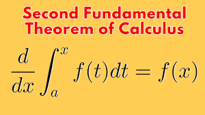
The Fundamental Theorem of Calculus establishes a crucial link between differentiation and integration.
It essentially states that these two operations are inverses of each other, and it provides a way to evaluate definite integrals using anti-derivatives.
Suppose that f is continuous at a closed interval [a, b] . If the function F is defined on a closed interval [a, b] by:
$$F(x) = \int_{a}^{x} f(t) dt $$
where a is a real number, Then F is the anti-derivative of f. in other words, F'(x) = f(x)
consider the relationships:
then
f(x) = x2and
Note: We use the dummy variable (t) in the integrand to avoid confusion with the upper limit x.
Sometimes the fundamental theorem of calculus is interpreted to mean that:
differentiation and integration are inverse processes to each other.
It follows that:
The fundamental theorem of calculus states that:
if f is continous on an open interval containing a and x and then we first integrate the function f and then differentiate with respect to x, then the result we get is the function f again.
In other words, the fundamental theorem of calculus argues that differentiation cancels the effect of intergration of continous f(x’).
in short:
For example
Example problem1
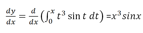
Use the fundamental theorem of calculus to find derivative of the following functions
(a)
solution
NOTE: The best way to benefit from this examples is trying the problem first before looking for answers and attempting again after checking your work against the answer.
Example problem2
(b)
solution to problem 2
Example problem 3
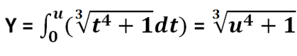
Find h'(x) given that :
solution
let y=h(x) and u=x2 and hence:
since u=x2;
and therefore:
By use of chain rule:
which implies u3sinu(2x) = (x2)3sin(x2)2x resulting to:
=2x7sin(x2)
Example problem 4
Consider the expression below, we exchange the limits in the intergral and then change the sign from positive to negative before using the fundamental theorem to solve it.
Example problems on fundamental theorem of calculus
We exchange limits and so the sign of the integral so that the upper limit is the valuable x.
Example problem 6
Use the fundamental theorem of calculus to solve:
Solution
splitting the integral about point zero we have:
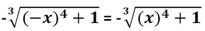
and then exchanging limits in the first integral;
let u=-x; first part of the expression above becomes;
from laws of differentiation du/dx=-1 and using chain rule;
Contains information related to marketing campaigns of the user. These are shared with Google AdWords / Google Ads when the Google Ads and Google Analytics accounts are linked together.
90 days
__utma
ID used to identify users and sessions
2 years after last activity
__utmt
Used to monitor number of Google Analytics server requests
10 minutes
__utmb
Used to distinguish new sessions and visits. This cookie is set when the GA.js javascript library is loaded and there is no existing __utmb cookie. The cookie is updated every time data is sent to the Google Analytics server.
30 minutes after last activity
__utmc
Used only with old Urchin versions of Google Analytics and not with GA.js. Was used to distinguish between new sessions and visits at the end of a session.
End of session (browser)
__utmz
Contains information about the traffic source or campaign that directed user to the website. The cookie is set when the GA.js javascript is loaded and updated when data is sent to the Google Anaytics server
6 months after last activity
__utmv
Contains custom information set by the web developer via the _setCustomVar method in Google Analytics. This cookie is updated every time new data is sent to the Google Analytics server.
2 years after last activity
__utmx
Used to determine whether a user is included in an A / B or Multivariate test.
18 months
_ga
ID used to identify users
2 years
_gali
Used by Google Analytics to determine which links on a page are being clicked
30 seconds
_ga_
ID used to identify users
2 years
_gid
ID used to identify users for 24 hours after last activity
24 hours
_gat
Used to monitor number of Google Analytics server requests when using Google Tag Manager